Remove the Lenovo Neptune Liquid to Air Module
Follow instructions in this section to remove the Lenovo Neptune Liquid to Air Module (L2AM).
This task must be operated by trained technicians that are certified by Lenovo Service. Do not attempt to remove or install the part without proper training and qualification.
About this task

Read Installation Guidelines and Safety inspection checklist to ensure that you work safely.
Power off the server and peripheral devices and disconnect the power cords and all external cables. See Power off the server.
Prevent exposure to static electricity, which might lead to system halt and loss of data, by keeping static-sensitive components in their static-protective packages until installation, and handling these devices with an electrostatic-discharge wrist strap or other grounding system.
If the server is installed in a rack, slide the server out on its rack slide rails to gain access to the top cover, or remove the server from the rack. See Remove the server from rack.
| Torque screwdriver type list | Screw Type |
|---|---|
| Torx T20 screwdriver | Torx T20 screw |
Procedure
- Disconnect the pump cable and leak detection cable of the L2AM module from the connector on the system board assembly. See Liquid to Air Module (L2AM) cable routing.Note
If you need to disconnect cables from the system board assembly, disengage all latches or release tabs on cable connectors first. Failing to release the tab before removing the cables will damage the cable sockets on the system board assembly. Any damage to the cable sockets might require replacing the system board assembly.
The connectors on your system board assembly might look different from those in the illustration, but the removal procedure is the same.
Press the release tab to release the connector.
Disengage the connector from the cable socket.
Figure 1. Disconnecting cables from the system board assembly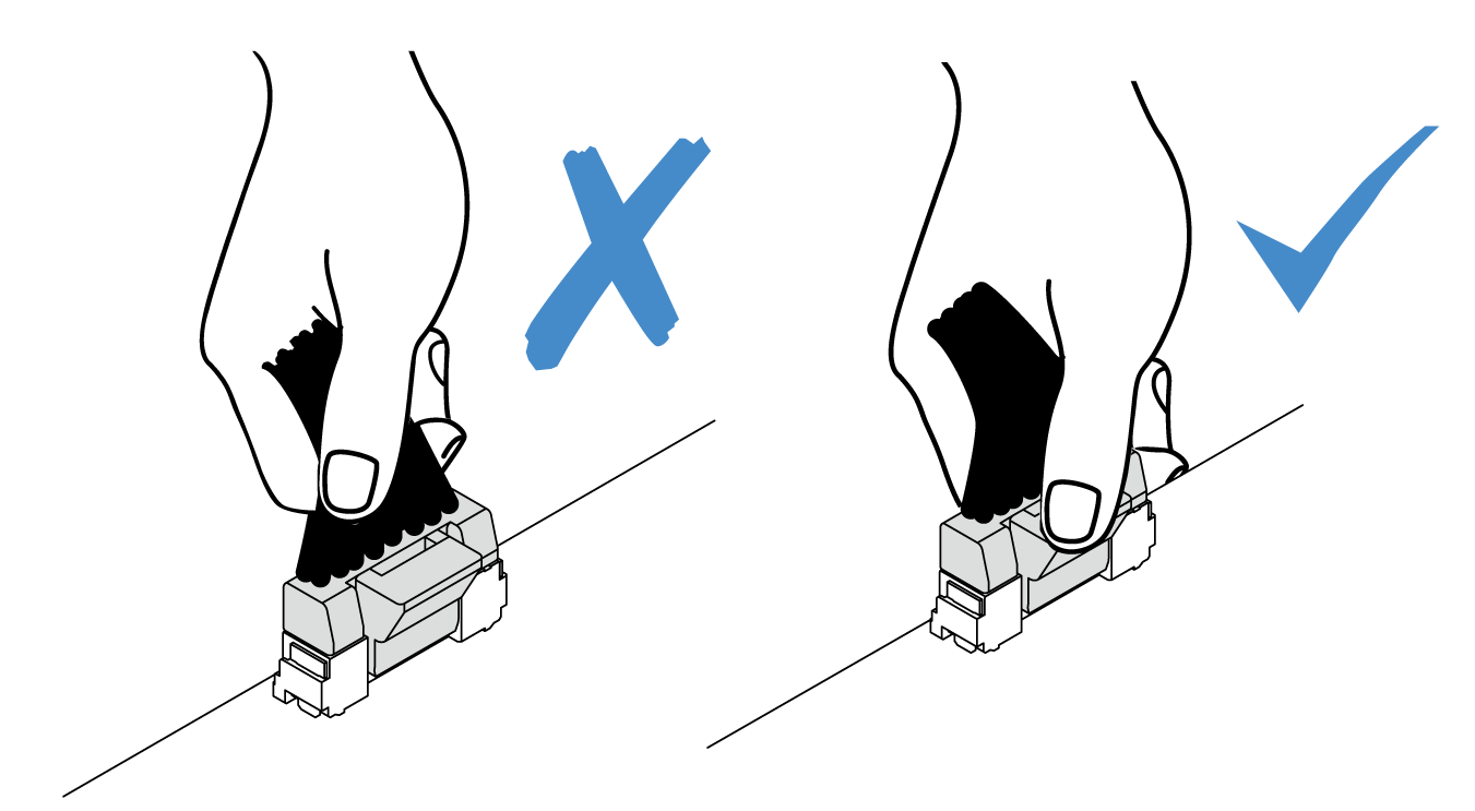
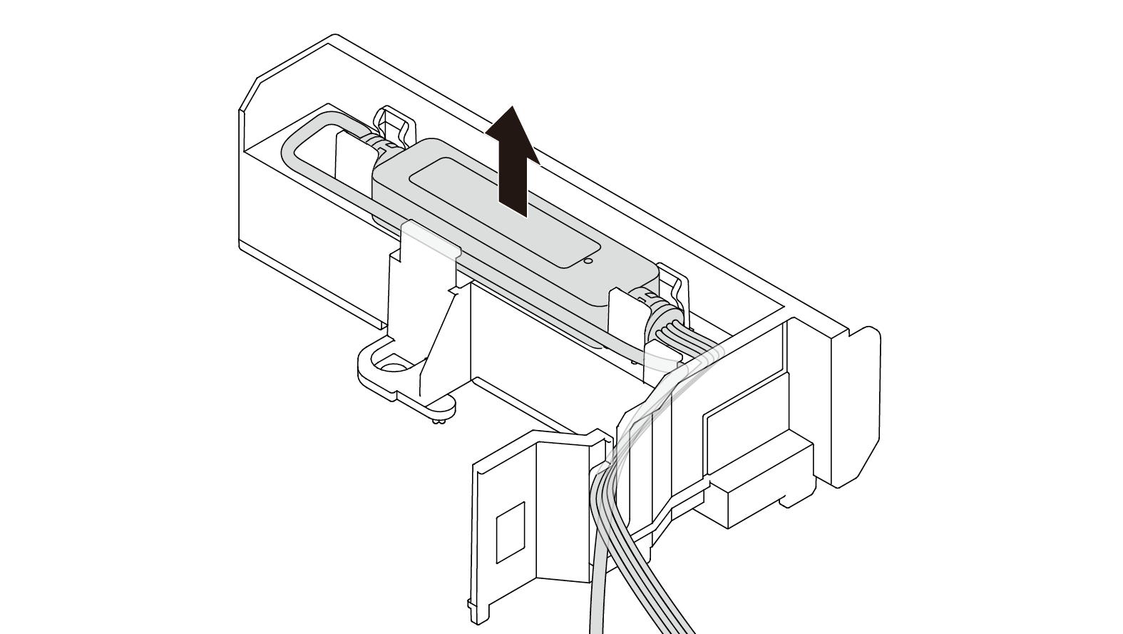
- Route the leak detection cable out of the cable clips on the leak detection module.
- Re-install the module handle (L2AM heat sink bracket) to the L2AM.
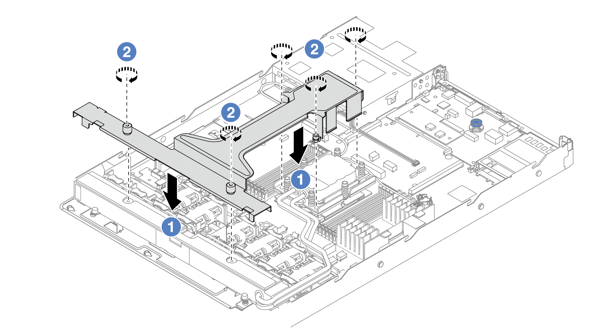
 Place the module handle (L2AM heat sink bracket) evenly on the L2AM and align screw holes.
 Tighten the five screws. Ensure that the screws are secured in place.
- Disengage the L2AM from processors.
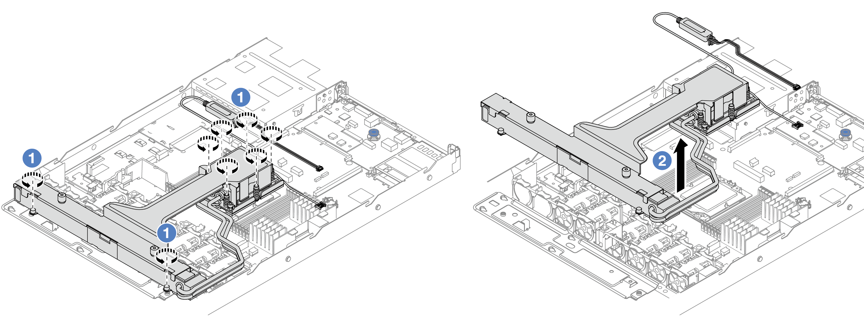
- Fully loosen the eight Torx T20 nuts in the removal sequence shown on the heat-sink label on the cold plate assembly and radiator.
- Grasp the middle of the module handle (L2AM heat sink bracket) and one T20 screw fastening the radiator to carefully lift the L2AM from the processor sockets. If the L2AM cannot be fully lifted out of the socket, further loosen the Torx T20 nuts and try lifting the L2AM again.
- Optionally, if you do not need to install a new L2AM module, remove the radiator tray from the chassis.
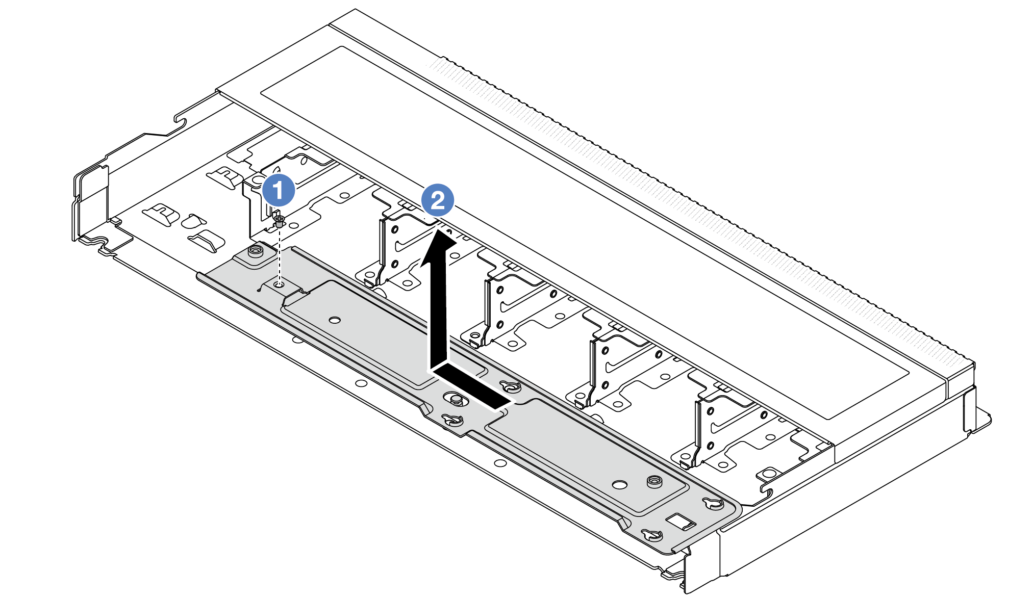
- Remove the screw on the radiator tray.
- Move the radiator tray to the left and lift it out of the chassis.
If you are instructed to return the component or optional device, follow all packaging instructions, and use any packaging materials for shipping that are supplied to you.
Demo video