Server model with ten 2.5-inch SAS/SATA/NVMe drives
Use this section to understand the connectors on the backplane and the internal cable routing for server model with ten 2.5-inch SAS/SATA/NVMe drives.
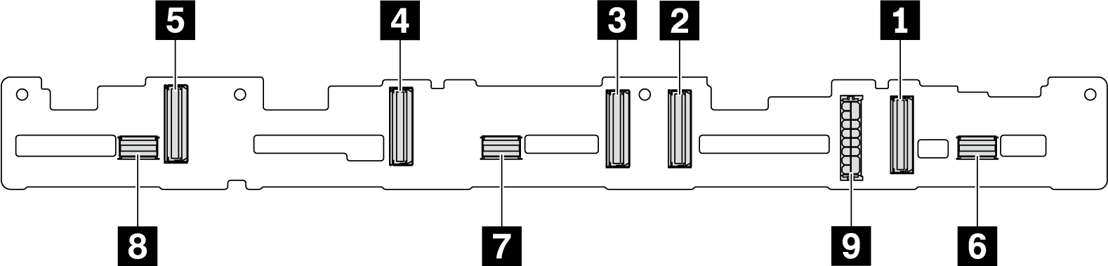
| 1 NVMe 0–1 connector | 2 NVMe 2–3 connector | 3 NVMe 4–5 connector | 4 NVMe 6–7 connector |
| 5 NVMe 8–9 connector | 6 SAS/SATA 0–3 | 7 SAS/SATA 4–7 | 8 SAS/SATA 8–9 |
| 9 Power connector |
For power cable connection, see Power/Sideband cable routing.
Ten 2.5-inch SAS/SATA/NVMe drives and one 16i RAID/HBA adapter
Ten 2.5-inch SATA/NVMe drives and rear SAS/SATA drive assembly
Ten 2.5-inch SAS/SATA/NVMe drives, rear SAS/SATA drive assembly and one 16i RAID/HBA adapter
Ten 2.5-inch SAS/SATA/NVMe drives, rear NVMe drive assembly and one 16i RAID/HBA adapter
Ten 2.5-inch NVMe drives, rear NVMe drive assembly and middle NVMe drive assembly
Ten 2.5-inch SAS/SATA/NVMe drives, middle NVMe drive assembly and one 16i RAID/HBA adapter
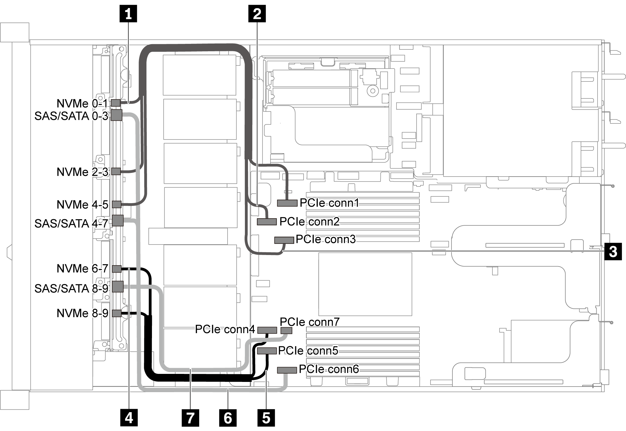
Ten 2.5-inch SATA/NVMe drives
| Cable | From | To |
|---|---|---|
| 1 NVMe signal cable for front backplane | NVMe 0–1 connector on the front backplane | PCIe connector 1 on the system board |
| 2 NVMe signal cable for front backplane | NVMe 2–3 connector on the front backplane | PCIe connector 2 on the system board |
| 3 NVMe signal cable for front backplane | NVMe 4–5 connector on the front backplane | PCIe connector 3 on the system board |
| 4 NVMe signal cable for front backplane | NVMe 6–7 connector on the front backplane | PCIe connector 4 on the system board |
| 5 NVMe signal cable for front backplane | NVMe 8–9 connector on the front backplane | PCIe connector 5 on the system board |
| 6 SAS signal cable for front backplane | SAS/SATA 0–3 and 4–7 connectors on the front backplane | PCIe connector 6 on the system board |
| 7 SAS signal cable for front backplane | SAS/SATA 8–9 connector on the front backplane | PCIe connector 7 on the system board |
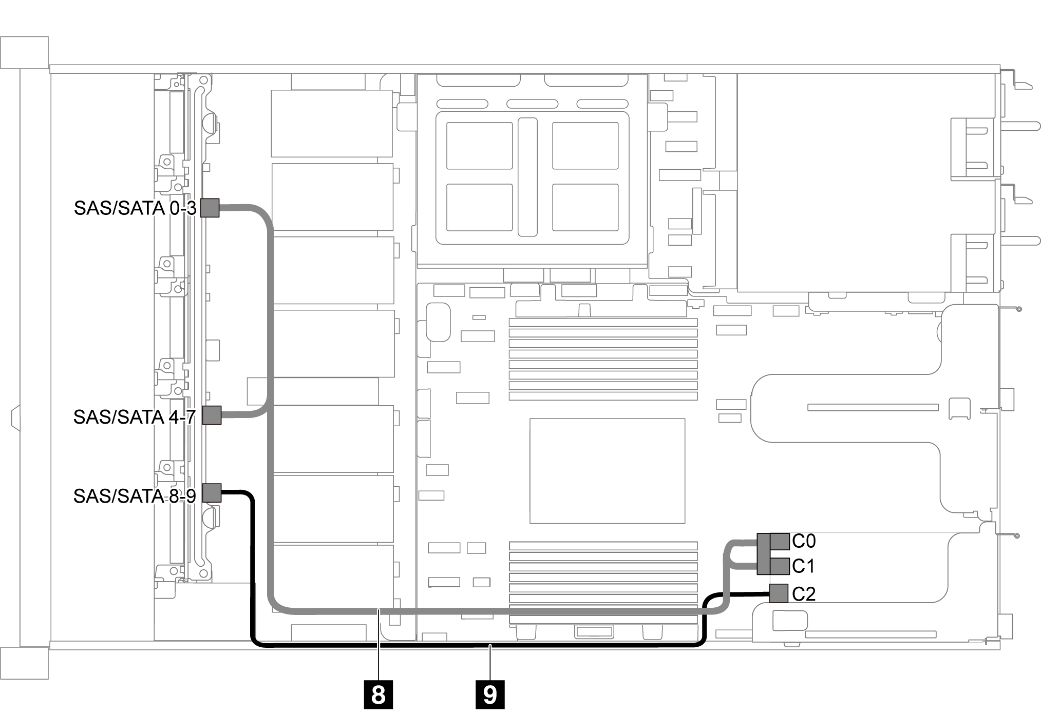
Ten 2.5-inch SAS/SATA/NVMe drives and one 16i RAID/HBA adapter
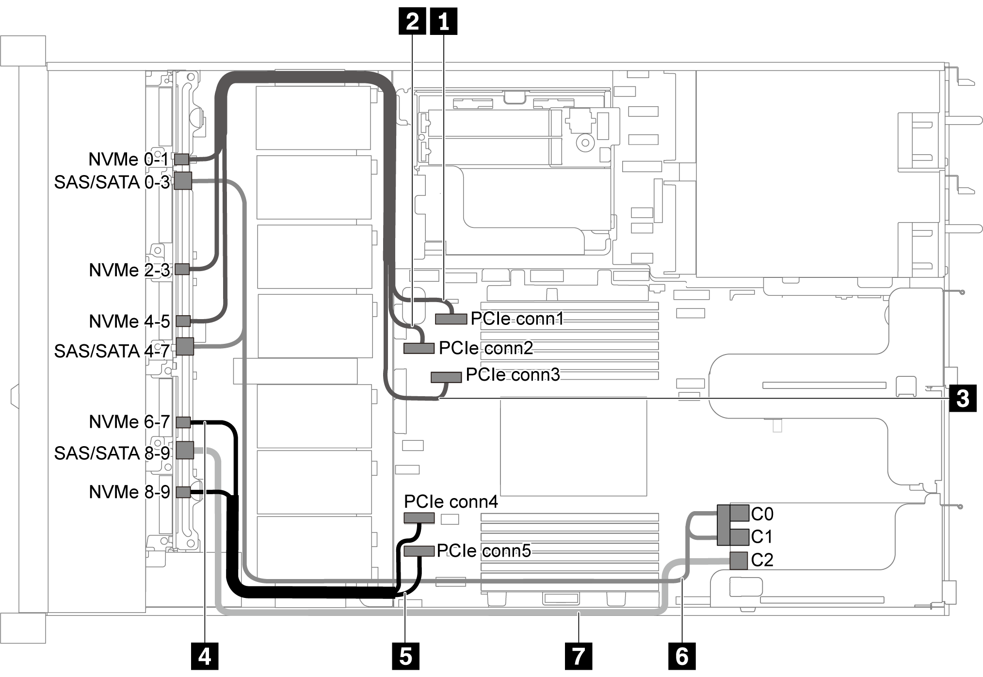
RAID/HBA adapters can be installed in PCIe slot 1 or internal riser assembly.
When a Gen 4 RAID/HBA adapter is installed, ensure that you use the corresponding Gen 4 cable:
ThinkSystem SR635 2.5” SAS/SATA/AnyBay 10-Bay X40 RAID Cable Kit
| Cable | From | To |
|---|---|---|
| 1 NVMe signal cable for front backplane | NVMe 0–1 connector on the front backplane | PCIe connector 1 on the system board |
| 2 NVMe signal cable for front backplane | NVMe 2–3 connector on the front backplane | PCIe connector 2 on the system board |
| 3 NVMe signal cable for front backplane | NVMe 4–5 connector on the front backplane | PCIe connector 3 on the system board |
| 4 NVMe signal cable for front backplane | NVMe 6–7 connector on the front backplane | PCIe connector 4 on the system board |
| 5 NVMe signal cable for front backplane | NVMe 8–9 connector on the front backplane | PCIe connector 5 on the system board |
| 6 SAS signal cable for front backplane | SAS/SATA 0–3 and SAS/SATA 4–7 connectors on the front backplane | The RAID/HBA adapter in PCIe slot 1
|
| 7 SAS signal cable for front backplane | SAS/SATA 8–9 connector on the front backplane | The RAID/HBA adapter in PCIe slot 1
|
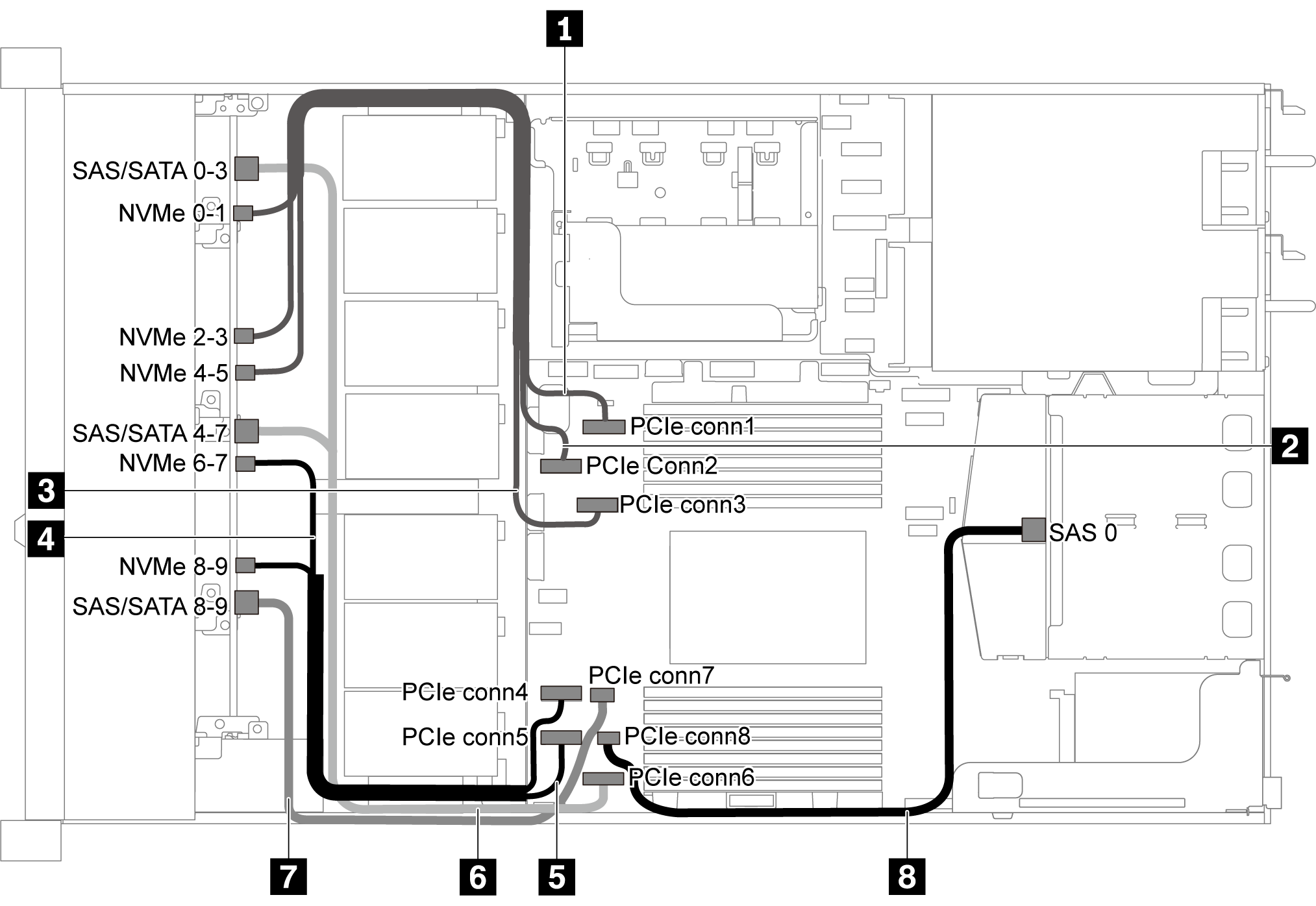
Ten 2.5-inch SATA/NVMe drives and rear SAS/SATA drive assembly
When the SAS/SATA backplanes are connected to PCIe connectors on the system board, only SATA drives are supported. No SAS drives are supported.
The cable routing illustration is based on the scenario that the rear hot-swap drive cage is installed. Depending on the model, the rear hot-swap drive cage might not be available fon your server.
| Cable | From | To |
|---|---|---|
| 1 NVMe signal cable for front backplane | NVMe 0–1 connector on the front backplane | PCIe connector 1 on the system board |
| 2 NVMe signal cable for front backplane | NVMe 2–3 connector on the front backplane | PCIe connector 2 on the system board |
| 3 NVMe signal cable for front backplane | NVMe 4–5 connector on the front backplane | PCIe connector 3 on the system board |
| 4 NVMe signal cable for front backplane | NVMe 6–7 connector on the front backplane | PCIe connector 4 on the system board |
| 5 NVMe signal cable for front backplane | NVMe 8–9 connector on the front backplane | PCIe connector 5 on the system board |
| 6 SAS signal cable for front backplane | SAS/SATA 0–3 and 4–7 connectors on the front backplane | PCIe connector 6 on the system board |
| 7 SAS signal cable for front backplane | SAS/SATA 8–9 connector on the front backplane | PCIe connector 7 on the system board |
| 8 SAS signal cable for rear backplane | SAS connector on the rear backplane | PCIe connector 8 on the system board |
Ten 2.5-inch SAS/SATA/NVMe drives, rear SAS/SATA drive assembly and one 16i RAID/HBA adapter
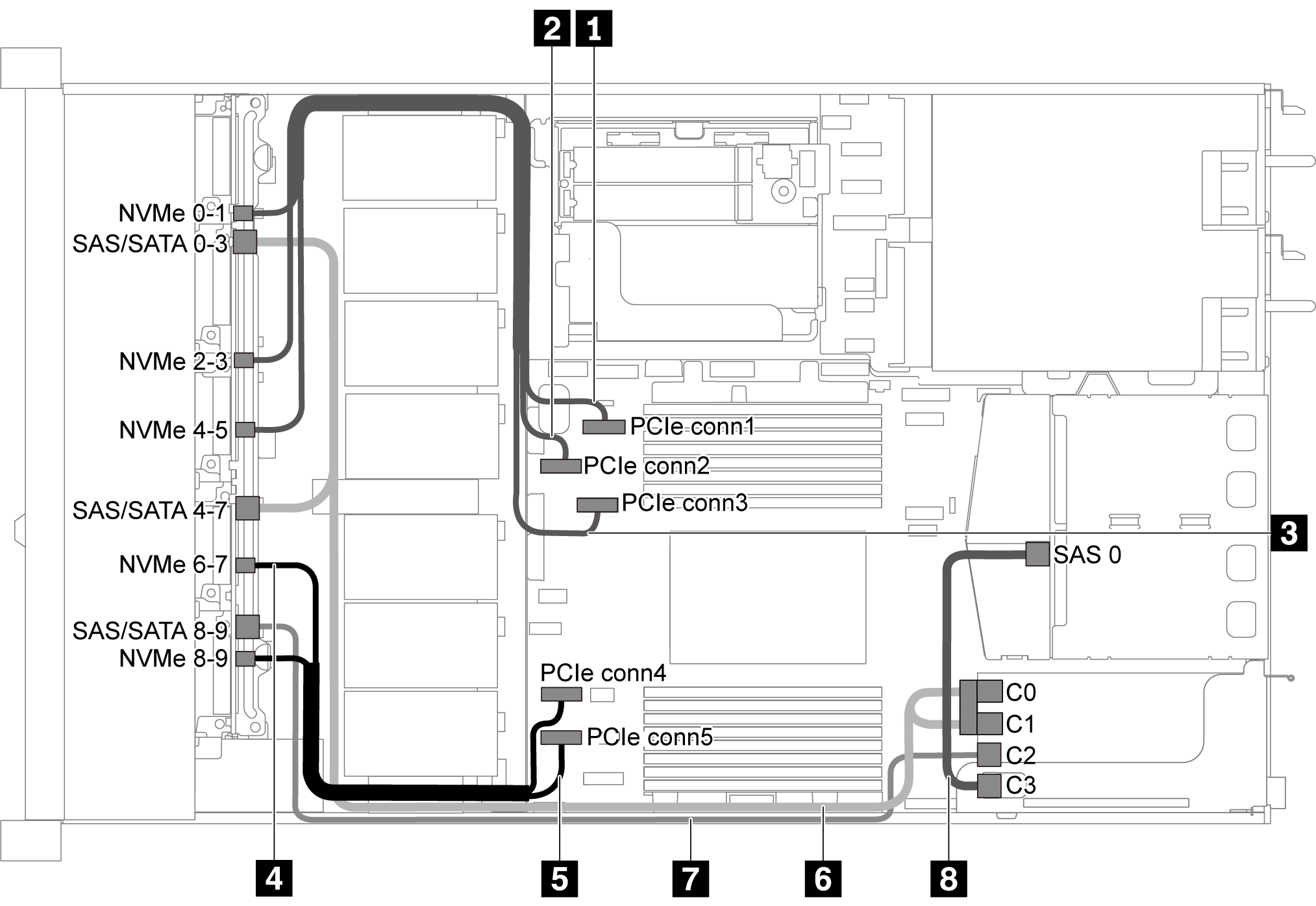
RAID/HBA adapters can be installed in PCIe slot 1 or internal riser assembly.
When a Gen 4 RAID/HBA adapter is installed, ensure that you use the corresponding Gen 4 cable:
For cable 6: ThinkSystem SR635 2.5” SAS/SATA/AnyBay 10-Bay X40 RAID Cable Kit
For cable 7 and 8: ThinkSystem SR635 2.5” SAS/SATA 2-Bay Rear Backplane X40 RAID Cable Kit
| Cable | From | To |
|---|---|---|
| 1 NVMe signal cable for front backplane | NVMe 0–1 connector on the front backplane | PCIe connector 1 on the system board |
| 2 NVMe signal cable for front backplane | NVMe 2–3 connector on the front backplane | PCIe connector 2 on the system board |
| 3 NVMe signal cable for front backplane | NVMe 4–5 connector on the front backplane | PCIe connector 3 on the system board |
| 4 NVMe signal cable for front backplane | NVMe 6–7 connector on the front backplane | PCIe connector 4 on the system board |
| 5 NVMe signal cable for front backplane | NVMe 8–9 connector on the front backplane | PCIe connector 5 on the system board |
| 6 SAS signal cable for front backplane | SAS/SATA 0–3 and SAS/SATA 4–7 connectors on the front backplane | The RAID/HBA adapter in PCIe slot 1
|
| 7 SAS signal cable for front backplane | SAS/SATA 8–9 connector on the front backplane | The RAID/HBA adapter in PCIe slot 1
|
| 8 SAS signal cable for rear backplane | SAS connector on the rear backplane | The RAID/HBA adapter in PCIe slot 1
|
Ten 2.5-inch SAS/SATA/NVMe drives, rear NVMe drive assembly and one 16i RAID/HBA adapter
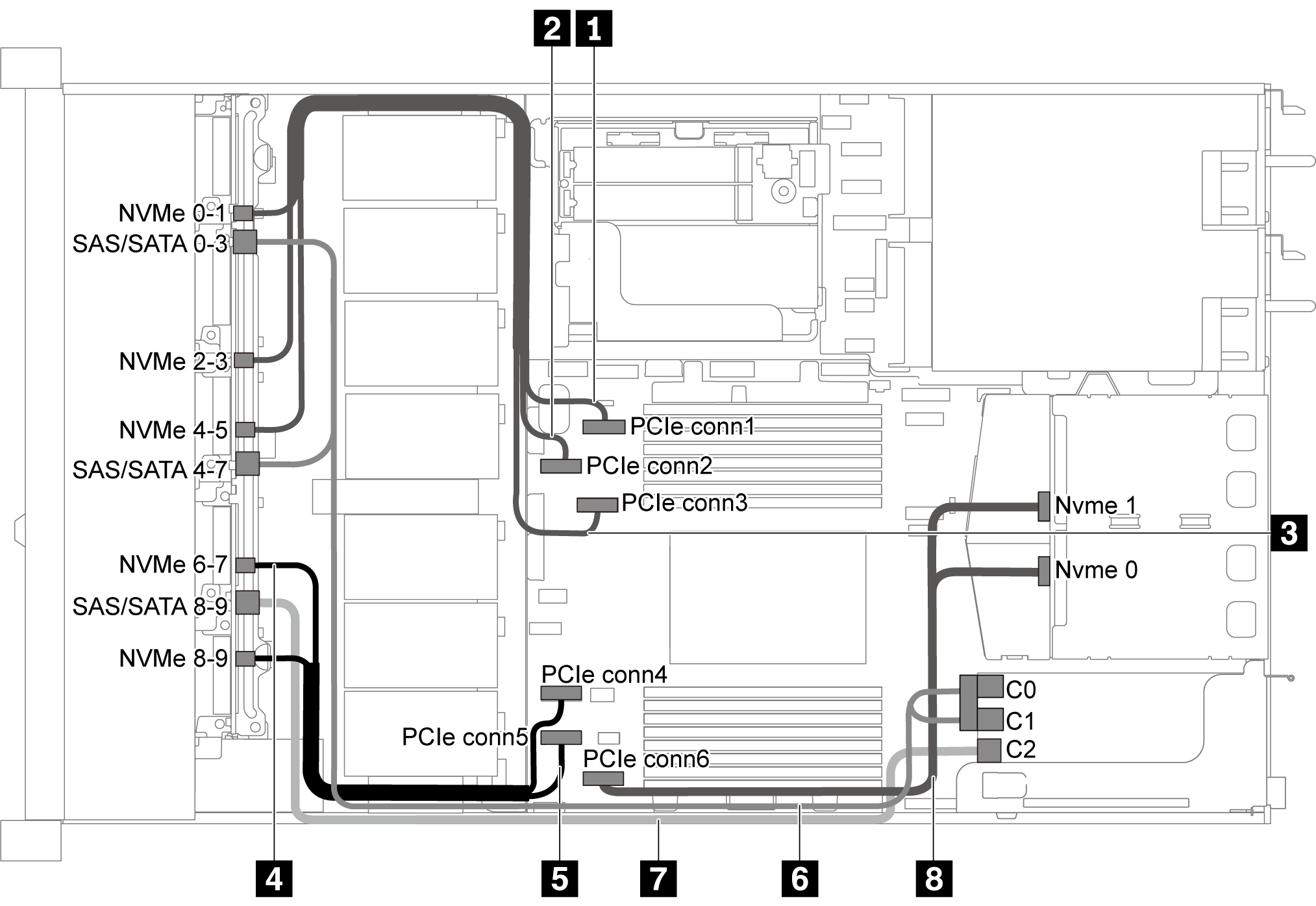
RAID/HBA adapters can be installed in PCIe slot 1 or internal riser assembly.
When a Gen 4 RAID/HBA adapter is installed, ensure that you use the corresponding Gen 4 cable:
ThinkSystem SR635 2.5” SAS/SATA/AnyBay 10-Bay X40 RAID Cable Kit
| Cable | From | To |
|---|---|---|
| 1 NVMe signal cable for front backplane | NVMe 0–1 connector on the front backplane | PCIe connector 1 on the system board |
| 2 NVMe signal cable for front backplane | NVMe 2–3 connector on the front backplane | PCIe connector 2 on the system board |
| 3 NVMe signal cable for front backplane | NVMe 4–5 connector on the front backplane | PCIe connector 3 on the system board |
| 4 NVMe signal cable for front backplane | NVMe 6–7 connector on the front backplane | PCIe connector 4 on the system board |
| 5 NVMe signal cable for front backplane | NVMe 8–9 connector on the front backplane | PCIe connector 5 on the system board |
| 6 SAS signal cable for front backplane | SAS/SATA 0–3 and SAS/SATA 4–7 connectors on the front backplane | The RAID/HBA adapter in PCIe slot 1
|
| 7 SAS signal cable for front backplane | SAS/SATA 8–9 connector on the front backplane | The RAID/HBA adapter in PCIe slot 1
|
| 8 NVMe signal cable for rear backplane | NVMe connectors on the rear backplane | PCIe connector 6 on the system board |
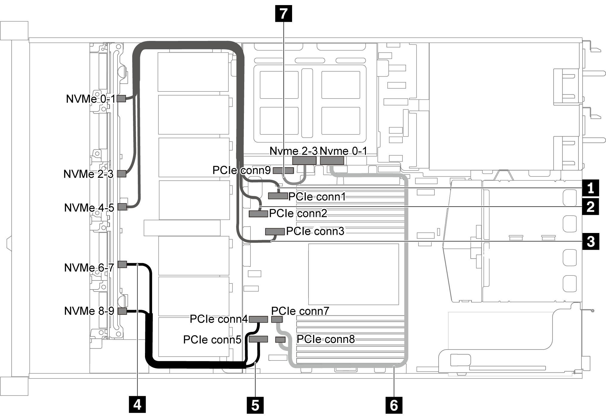
Ten 2.5-inch SAS/SATA/NVMe drives, rear SAS/SATA drive assembly, middle NVMe drive assembly and one 16i RAID/HBA adapter
The cable routing illustration is based on the scenario that the rear hot-swap drive cage and middle NVMe drive assembly are installed. Depending on the model, the rear hot-swap drive cage and middle NVMe drive assembly might not be available on your server.
The following two illustrations are for the same configuration.
| Cable | From | To |
|---|---|---|
| 1 NVMe signal cable for front backplane | NVMe 0–1 connector on the front backplane | PCIe connector 1 on the system board |
| 2 NVMe signal cable for front backplane | NVMe 2–3 connector on the front backplane | PCIe connector 2 on the system board |
| 3 NVMe signal cable for front backplane | NVMe 4–5 connector on the front backplane | PCIe connector 3 on the system board |
| 4 NVMe signal cable for front backplane | NVMe 6–7 connector on the front backplane | PCIe connector 4 on the system board |
| 5 NVMe signal cable for front backplane | NVMe 8–9 connector on the front backplane | PCIe connector 5 on the system board |
| 6 NVMe signal cable for middle backplane | NVMe 0–1 connector on the middle backplane | PCIe connector 7 and PCIe connector 8 on the system board |
| 7 NVMe signal cable for middle backplane | NVMe 2–3 connector on the middle backplane | PCIe connector 9 on the system board |
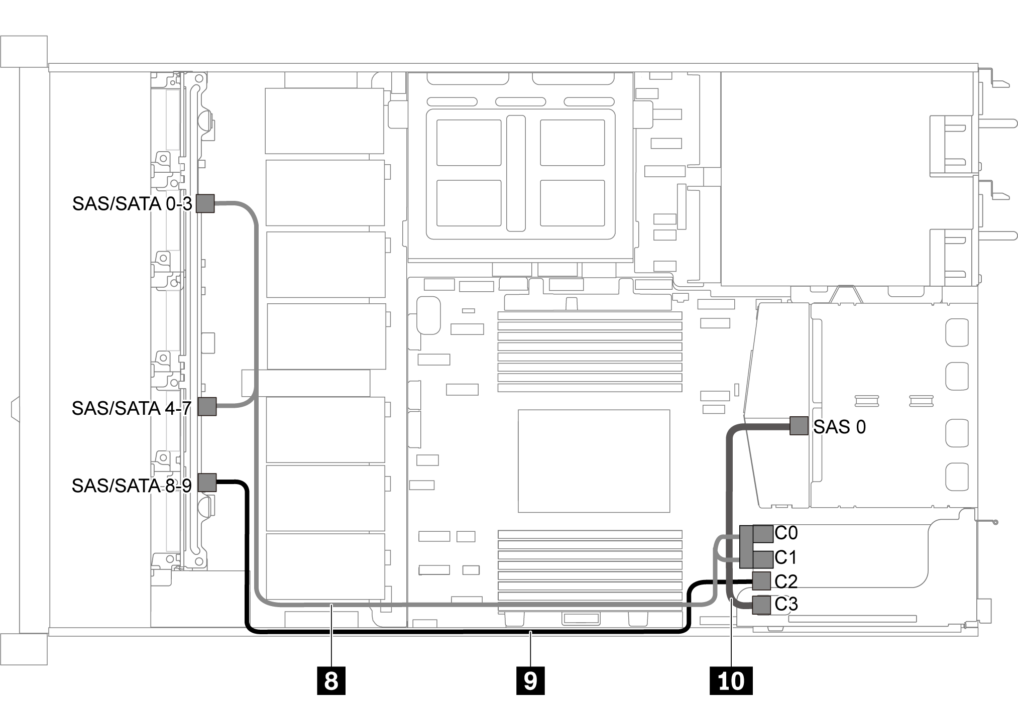
When a Gen 4 RAID/HBA adapter is installed, ensure that you use the corresponding Gen 4 cable:
For cable 8: ThinkSystem SR635 2.5” SAS/SATA/AnyBay 10-Bay X40 RAID Cable Kit
For cable 9 and 10: ThinkSystem SR635 2.5” SAS/SATA 2-Bay Rear Backplane X40 RAID Cable Kit
| Cable | From | To |
|---|---|---|
| 8 SAS signal cable for front backplane | SAS/SATA 0–3 and SAS/SATA 4–7 connectors on the front backplane | The RAID/HBA adapter in PCIe slot 1
|
| 9 SAS signal cable for front backplane | SAS/SATA 8–9 connector on the front backplane | The RAID/HBA adapter in PCIe slot 1
|
| 10 SAS signal cable for rear backplane | SAS 0 connector on the middle backplane | The RAID/HBA adapter in PCIe slot 1
|
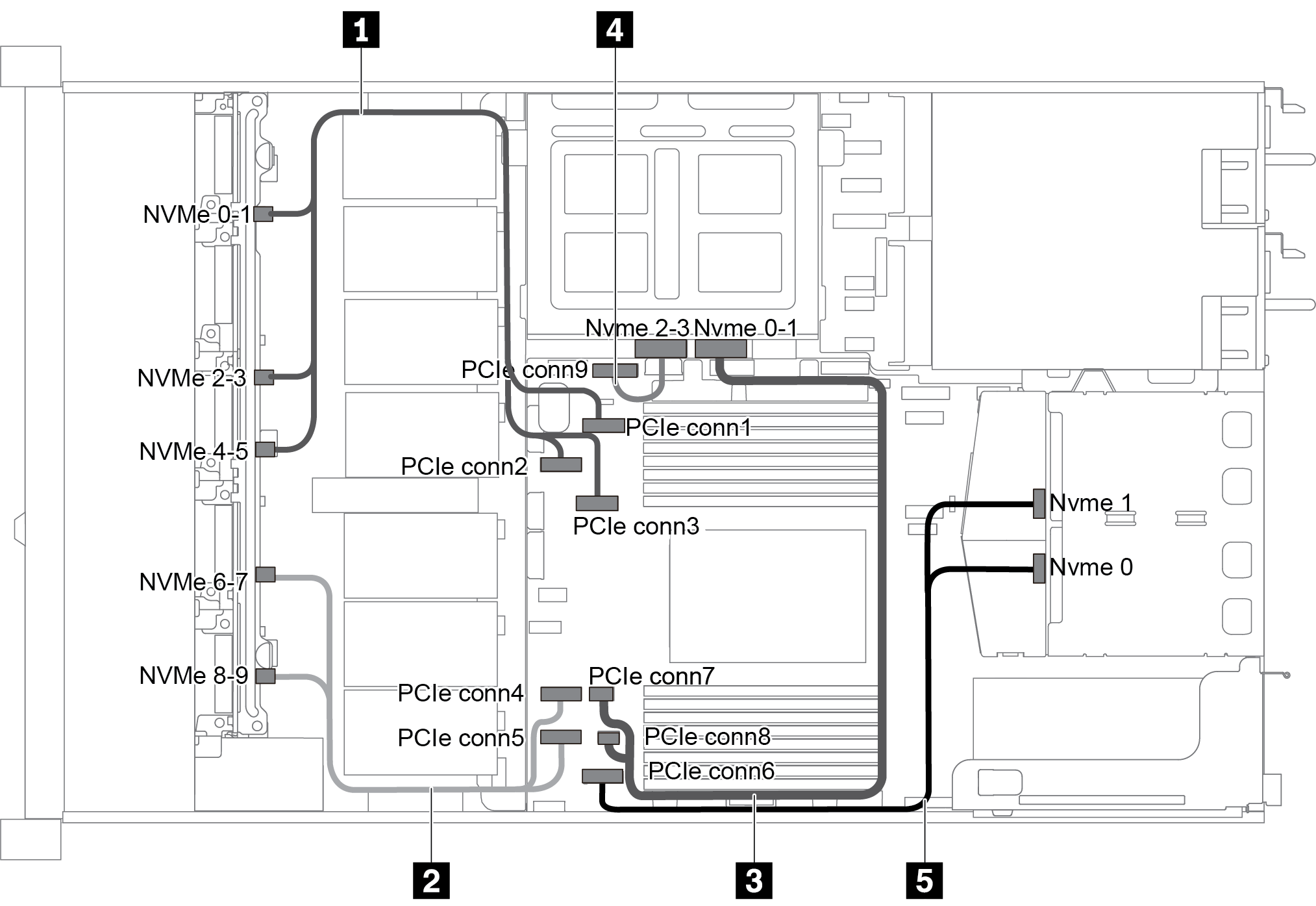
Ten 2.5-inch NVMe drives, rear NVMe drive assembly and middle NVMe drive assembly
Ten 2.5-inch NVMe drives: Connect Cable 1 and Cable 2
Ten 2.5-inch NVMe drives and rear NVMe drive assembly: Connect Cable 1 , Cable 2, and Cable 5
Ten 2.5-inch NVMe drives and middle NVMe drive assembly: Connect Cable 1 , Cable 2, Cable 3, and Cable 4
| Cable | From | To |
|---|---|---|
| 1 NVMe signal cable for front backplane | NVMe 0–1, NVMe 2–3, and NVMe 4–5 connectors on the front backplane | PCIe connector 1, PCIe connector 2, and PCIe connector 3 on the system board |
| 2 NVMe signal cable for front backplane | NVMe 6–7 and NVMe 8–9 connectors on the front backplane | PCIe connector 4 and PCIe connector 5 on the system board |
| 3 NVMe signal cable for middle backplane | NVMe 0–1 connector on the middle backplane | PCIe connector 7 and PCIe connector 8 on the system board |
| 4 NVMe signal cable for middle backplane | NVMe 2–3 connector on the middle backplane | PCIe connector 9 on the system board |
| 5 NVMe signal cable for rear backplane | NVMe 0 and NVMe 1 connectors on the rear backplane | PCIe connector 6 on the system board |
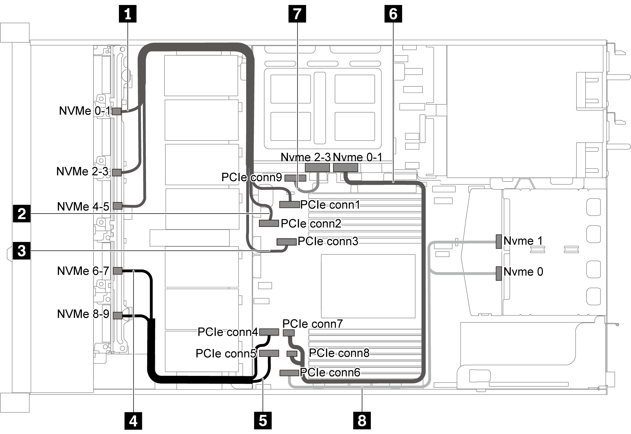
Ten 2.5-inch SAS/SATA/NVMe drives, rear NVMe drive assembly, middle NVMe drive assembly and one 16i RAID/HBA adapter
The cable routing illustration is based on the scenario that the rear hot-swap drive cage and middle NVMe drive assembly are installed. Depending on the model, the rear hot-swap drive cage and middle NVMe drive assembly might not be available on your server.
The following two illustrations are for the same configuration.
| Cable | From | To |
|---|---|---|
| 1 NVMe signal cable for front backplane | NVMe 0–1 connector on the front backplane | PCIe connector 1 on the system board |
| 2 NVMe signal cable for front backplane | NVMe 2–3 connector on the front backplane | PCIe connector 2 on the system board |
| 3 NVMe signal cable for front backplane | NVMe 4–5 connector on the front backplane | PCIe connector 3 on the system board |
| 4 NVMe signal cable for front backplane | NVMe 6–7 connector on the front backplane | PCIe connector 4 on the system board |
| 5 NVMe signal cable for front backplane | NVMe 8–9 connector on the front backplane | PCIe connector 5 on the system board |
| 6 NVMe signal cable for middle backplane | NVMe 0–1 connector on the middle backplane | PCIe connector 7 and PCIe connector 8 on the system board |
| 7 NVMe signal cable for middle backplane | NVMe 2–3 connector on the middle backplane | PCIe connector 9 on the system board |
| 8 NVMe signal cable for rear backplane | NVMe 0 and NVMe 1 connectors on the rear backplane | PCIe connector 6 on the system board |
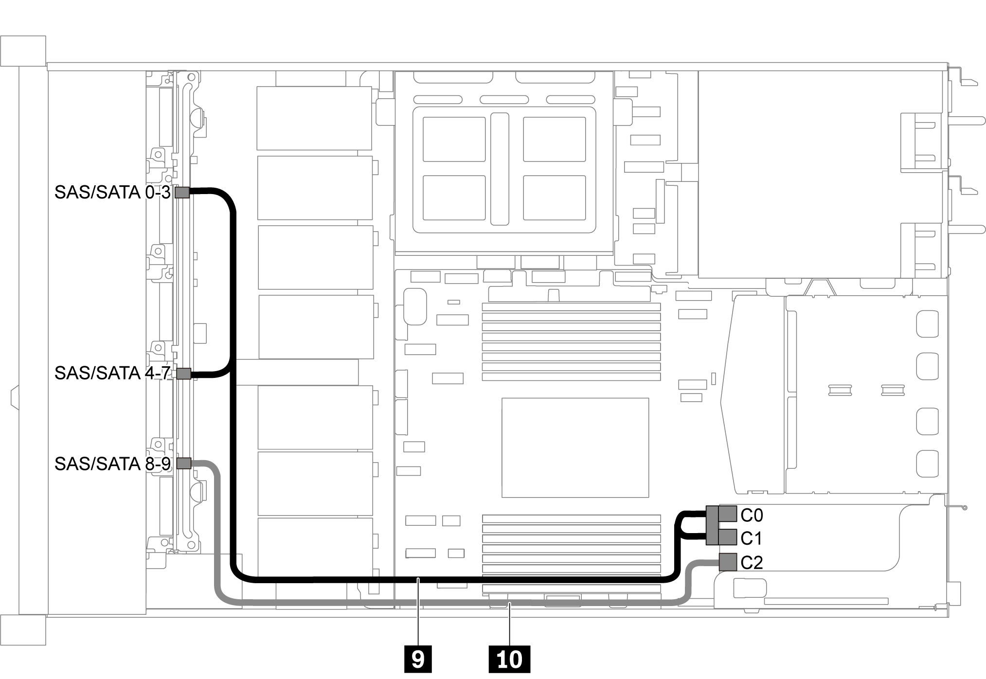
When a Gen 4 RAID/HBA adapter is installed, ensure that you use the corresponding Gen 4 cable:
ThinkSystem SR635 2.5” SAS/SATA/AnyBay 10-Bay X40 RAID Cable Kit
| Cable | From | To |
|---|---|---|
| 9 SAS signal cable for front backplane | SAS/SATA 0–3 and SAS/SATA 4–7 connectors on the front backplane | The RAID/HBA adapter in PCIe slot 1
|
| 10 SAS signal cable for front backplane | SAS/SATA 8–9 connector on the front backplane | The RAID/HBA adapter in PCIe slot 1
|
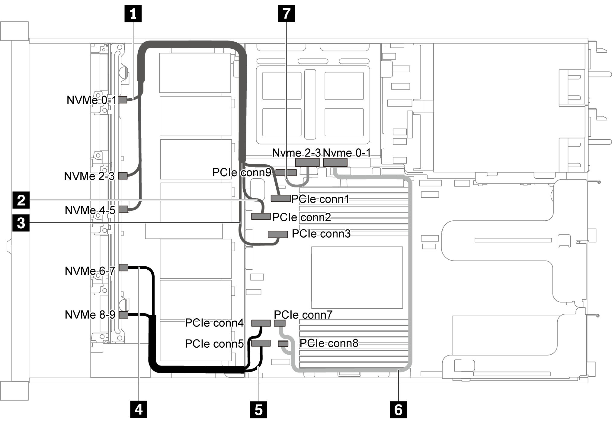
Ten 2.5-inch SAS/SATA/NVMe drives, middle NVMe drive assembly and one 16i RAID/HBA adapter
The cable routing illustration is based on the scenario that the middle NVMe drive assembly is installed. Depending on the model, the middle NVMe drive assembly might not be available on your server.
The following two illustrations are for the same configuration.
| Cable | From | To |
|---|---|---|
| 1 NVMe signal cable for front backplane | NVMe 0–1 connector on the front backplane | PCIe connector 1 on the system board |
| 2 NVMe signal cable for front backplane | NVMe 2–3 connector on the front backplane | PCIe connector 2 on the system board |
| 3 NVMe signal cable for front backplane | NVMe 4–5 connector on the front backplane | PCIe connector 3 on the system board |
| 4 NVMe signal cable for front backplane | NVMe 6–7 connector on the front backplane | PCIe connector 4 on the system board |
| 5 NVMe signal cable for front backplane | NVMe 8–9 connector on the front backplane | PCIe connector 5 on the system board |
| 6 NVMe signal cable for middle backplane | NVMe 0–1 connector on the middle backplane | PCIe connector 7 on the system board |
| 7 NVMe signal cable for middle backplane | NVMe 2–3 connector on the middle backplane | PCIe connector 9 on the system board |
When a Gen 4 RAID/HBA adapter is installed, ensure that you use the corresponding Gen 4 cable:
ThinkSystem SR635 2.5” SAS/SATA/AnyBay 10-Bay X40 RAID Cable Kit
| Cable | From | To |
|---|---|---|
| 8 SAS signal cable for front backplane | SAS/SATA 0–3 and SAS/SATA 4–7 connectors on the front backplane | The RAID/HBA adapter in PCIe slot 1
|
| 9 SAS signal cable for front backplane | SAS/SATA 8–9 connector on the front backplane | The RAID/HBA adapter in PCIe slot 1
|