Power/Sideband cable routing
Use the section to understand the power and sideband cable routing for CPU, backplanes, PIB board, fan board, internal drive assembly, and rear drive cage.
Figure 1. 2.5-inch chaiss-1
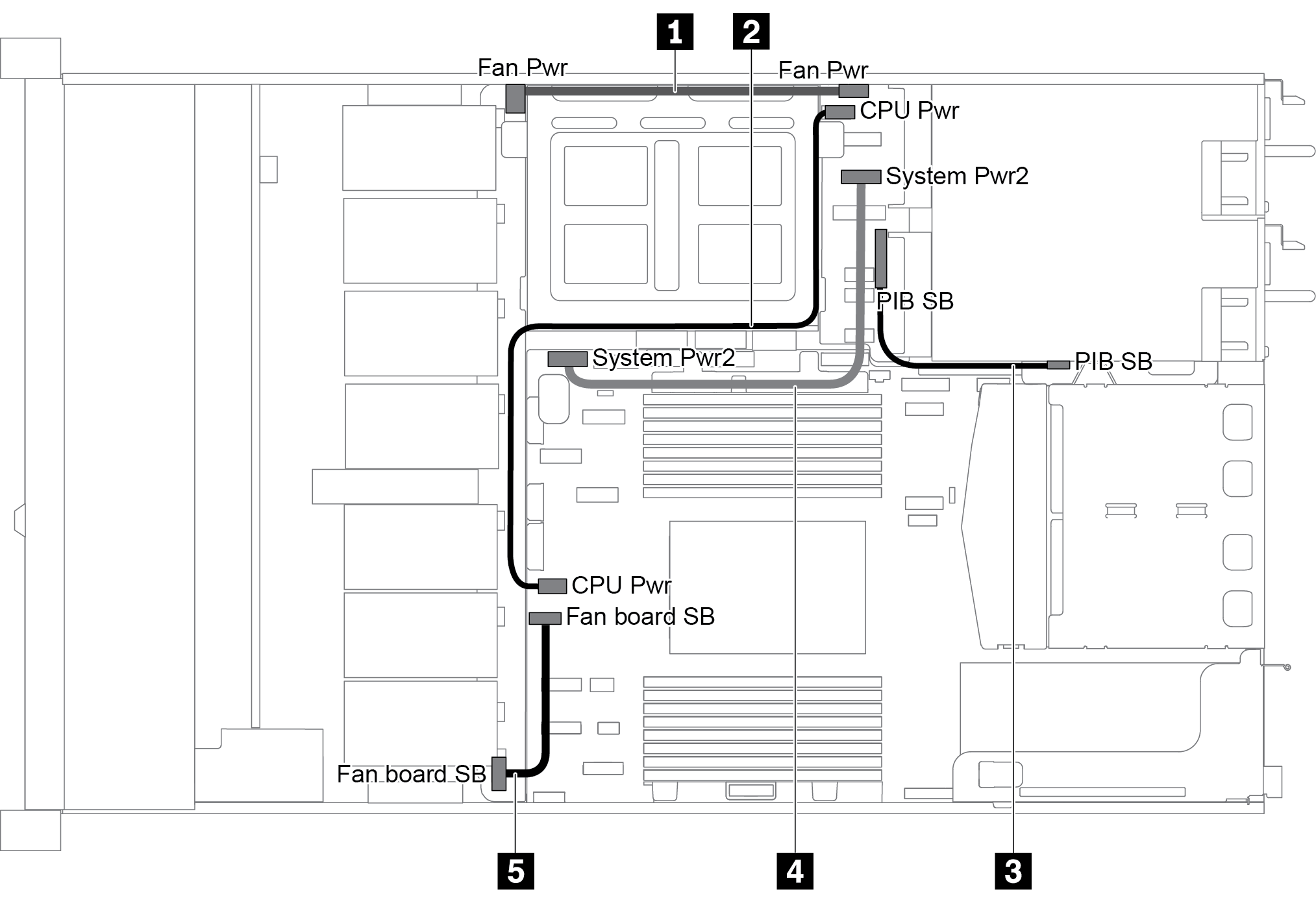
| Cable | From | To |
|---|---|---|
| 1 | Fan board power connector on the fan board | Fan board power connector on the PIB board |
| 2 | CPU power connector on the PIB board | CPU power connector on the system board |
| 3 | PIB sideband connector on the PIB board | PIB sideband connector on the system board |
| 4 | System power connector 2 on the PIB board | System power connector 2 on the system board |
| 5 | Sideband connector on the fan board | Fan sideband connector on the system board |
Figure 2. 2.5-inch chaiss-2
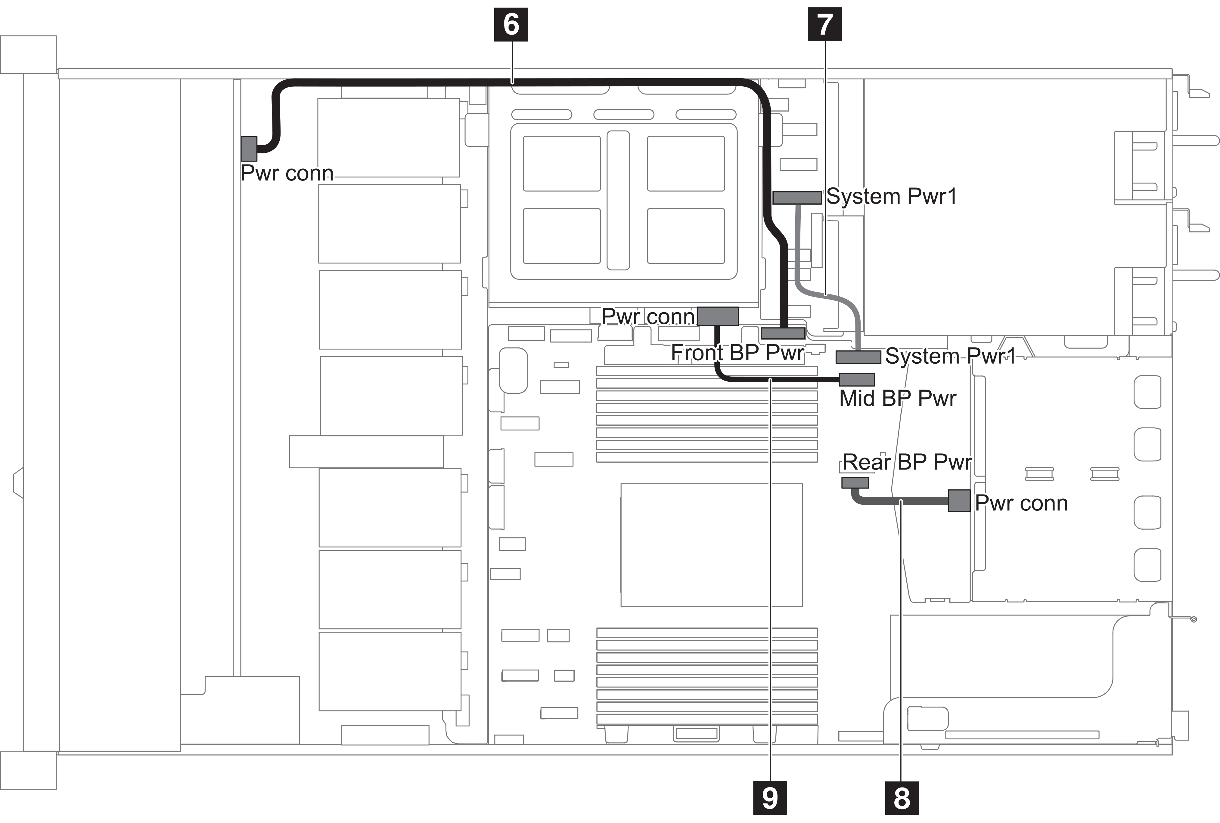
| Cable | From | To |
|---|---|---|
| 6 | Front backplane power connector on the front backplane | Front backplane power connector on the system board |
| 7 | System power connector 1 on the PIB board | System power connector 1 on the system board |
| 8 | Power connector on the rear backplane | Rear backplane power connector on the system board |
| 9 | Power connector on the middle backplane | Middle backplane power connector on the system board |
Figure 3. 3.5-inch chaiss
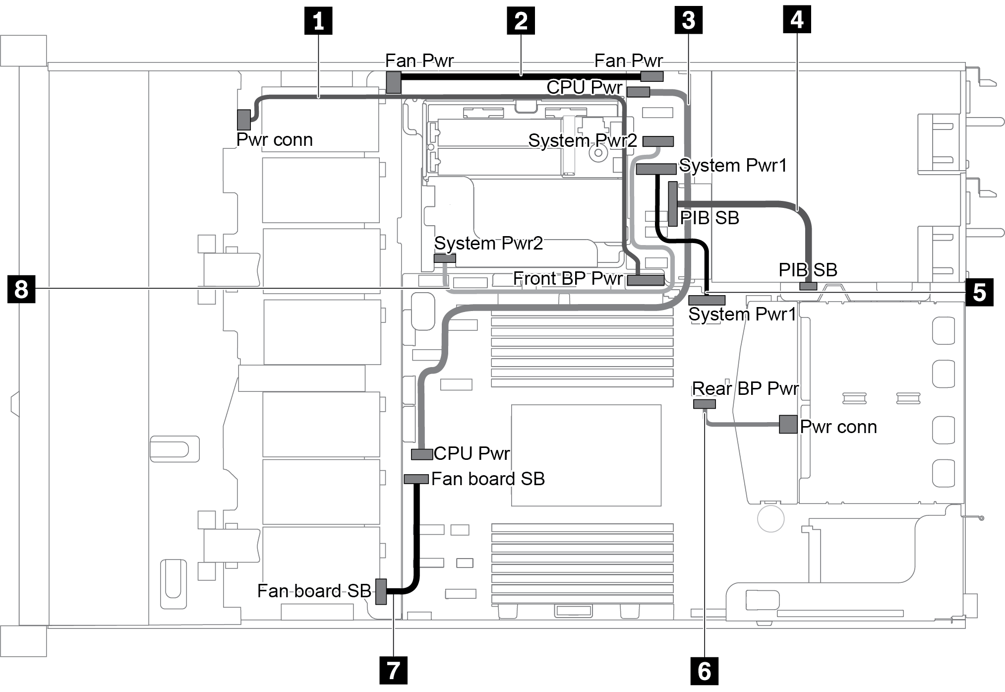
| Cable | From | To |
|---|---|---|
| 1 | Power connector on the front backplane | Front backplane power connector on the system board |
| 2 | Fan board power connector on the fan board | Fan board power connector on the PIB board |
| 3 | CPU power connector on the PIB board | CPU power connector on the system board |
| 4 | PIB sideband connector on the PIB board | PIB sideband connector on the system board |
| 5 | System power connector 1 on the PIB board | System power connector 1 on the system board |
| 6 | Power connector on the rear backplane | Rear backplane power connector on the system board |
| 7 | Sideband connector on the fan board | Fan sideband connector on the system board |
| 8 | System power connector 2 on the PIB board | System power connector 2 on the system board |
Give documentation feedback