8/16/24 x 2.5" AnyBay/NVMe
This topic provides cable routing information for the 8 x 2.5"/16 x 2.5"/24 x 2.5" AnyBay/NVMe configuration.
The configuration numbers in the table below are for descriptive purposes only.
| BP config. | Storage controller | Config. No. |
|---|---|---|
| 8 x 2.5" NVMe (BP1) | N/A | 1 |
| 8 x 2.5" AnyBay (BP1) | 1 x SFF 8i/16i | 2 |
| 1 x CFF 16i | 3 | |
| 16 x 2.5" NVMe (BP1 + BP2) | N/A | 4 |
| 24 x 2.5" NVMe (BP1 + BP2 + BP3) | N/A | 5 |
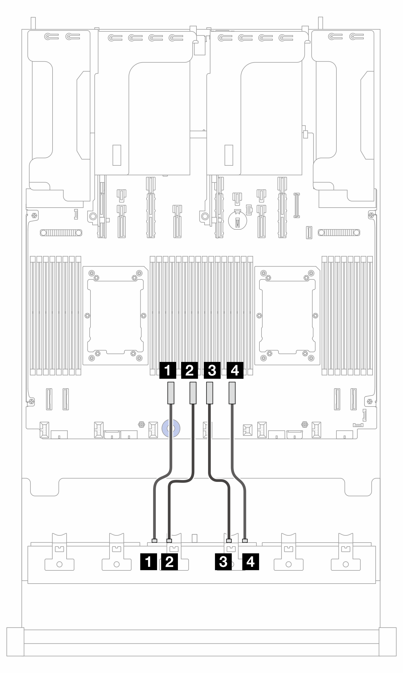
NVMe cable routing (config. 1/2/3)
Figure 1. Cable routing when two processors are installed 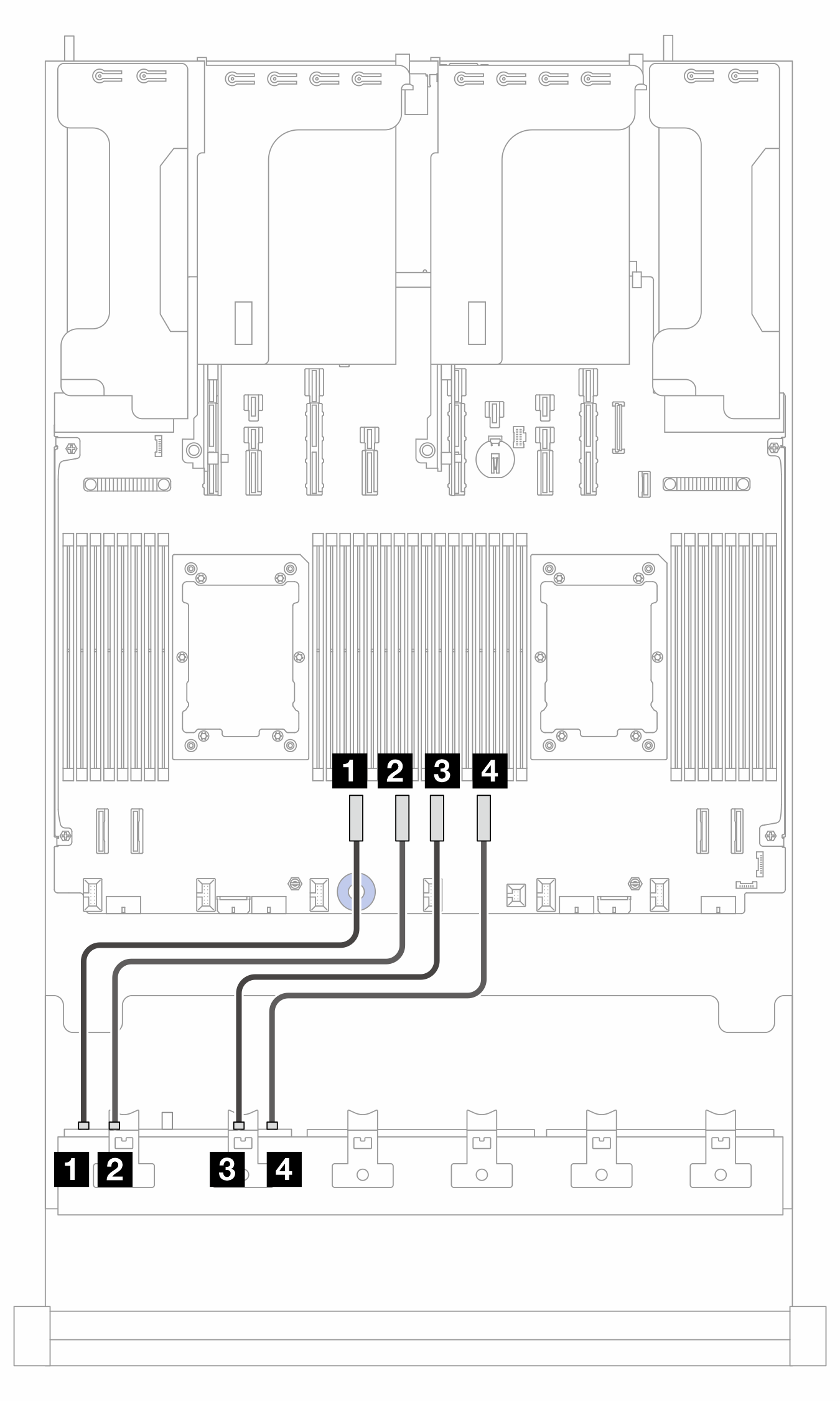 | Figure 2. Cable routing when one processor is installed 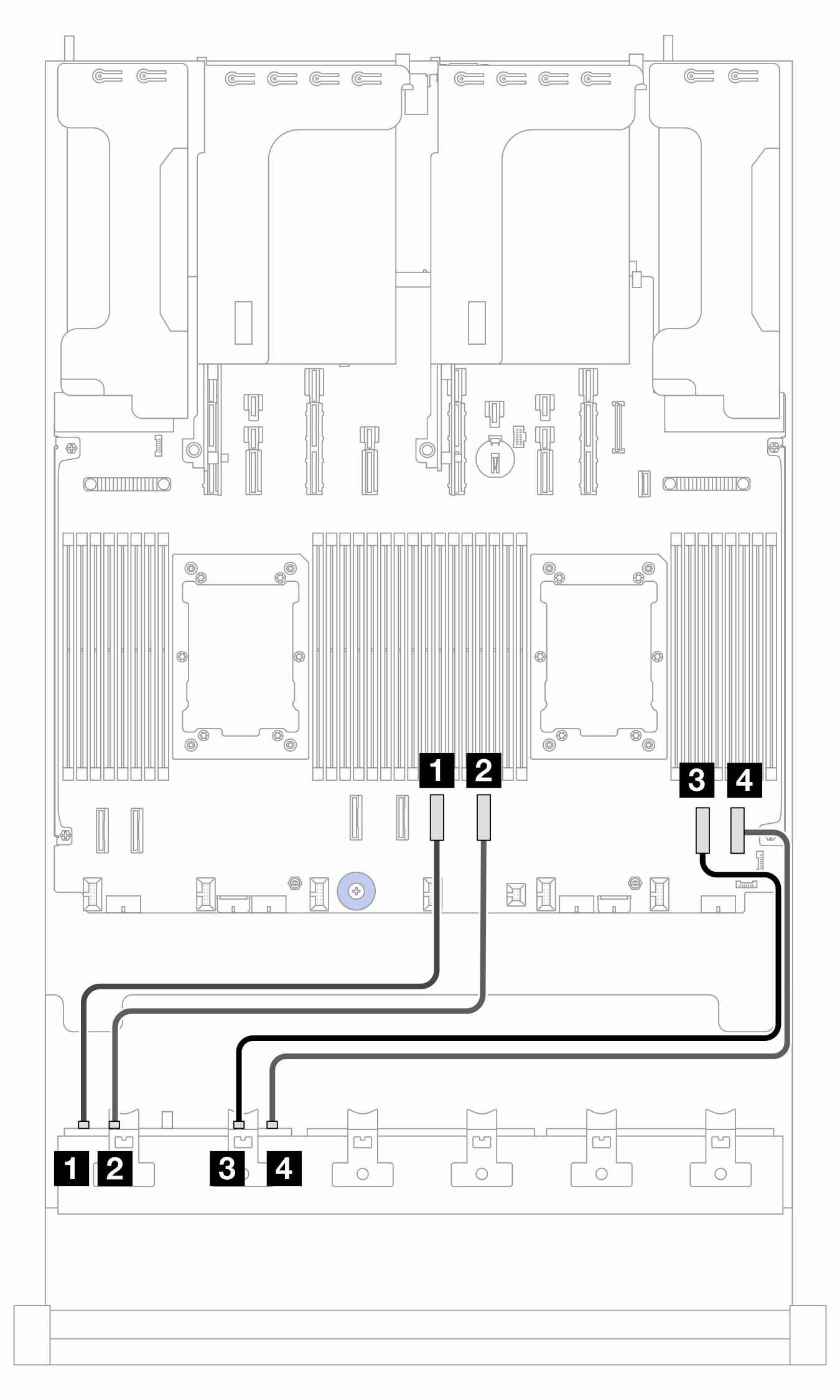 |
2P: two processors; 1P: one processor
| From (BP1) | To (processor board) | Cable length | |
|---|---|---|---|
| 2P | 1P | ||
| 1 NVMe 0-1 | 1 PCIe 6 | 1 PCIe 4 |
|
| 2 NVMe 2-3 | 2 PCIe 5 | 2 PCIe 3 |
|
| 3 NVMe 4-5 | 3 PCIe 4 | 3 PCIe 2 |
|
| 4 NVMe 6-7 | 4 PCIe 3 | 4 PCIe 1 |
|
Cable routing to SFF 8i/16i adapter (config. 2)
Note
The location of the adapter and cable connectors on the adapter may differ from those shown in the illustration. For details, see the table below.
Figure 3. Cable routing to SFF 8i/16i adapter
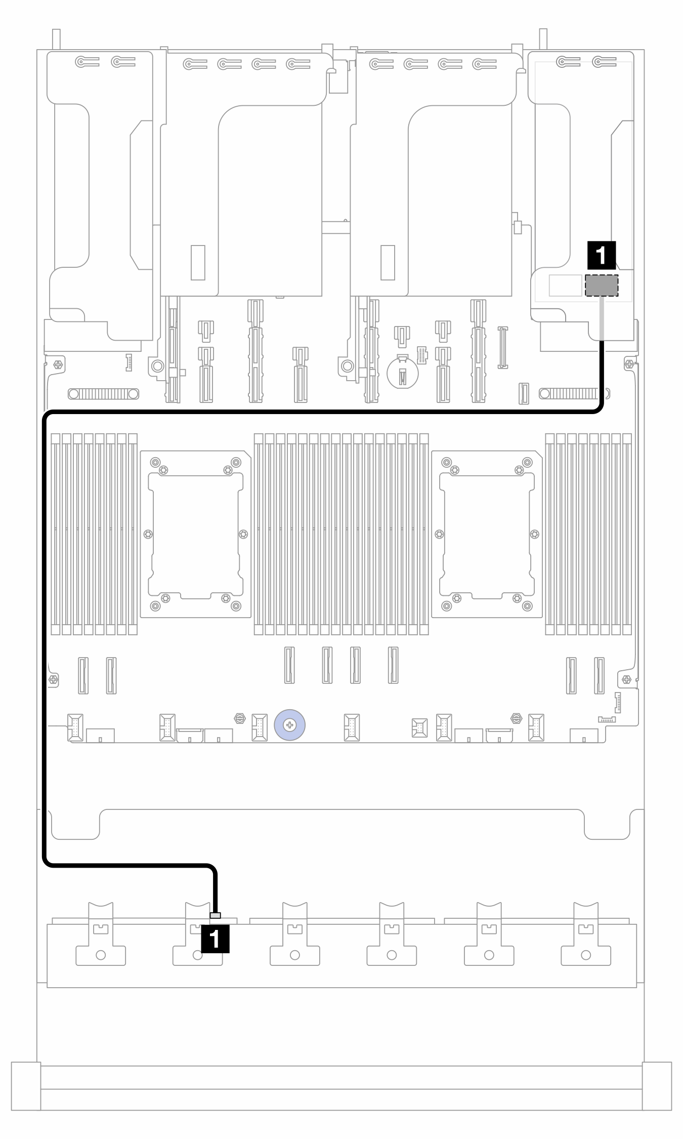
| From | To | Cable length |
|---|---|---|
| 1 BP1: SAS | 1 8i/16i adapter:
| 900 mm |
Cable routing to CFF 16i adapter (config. 3)
Figure 4. Cable routing when two processors are installed 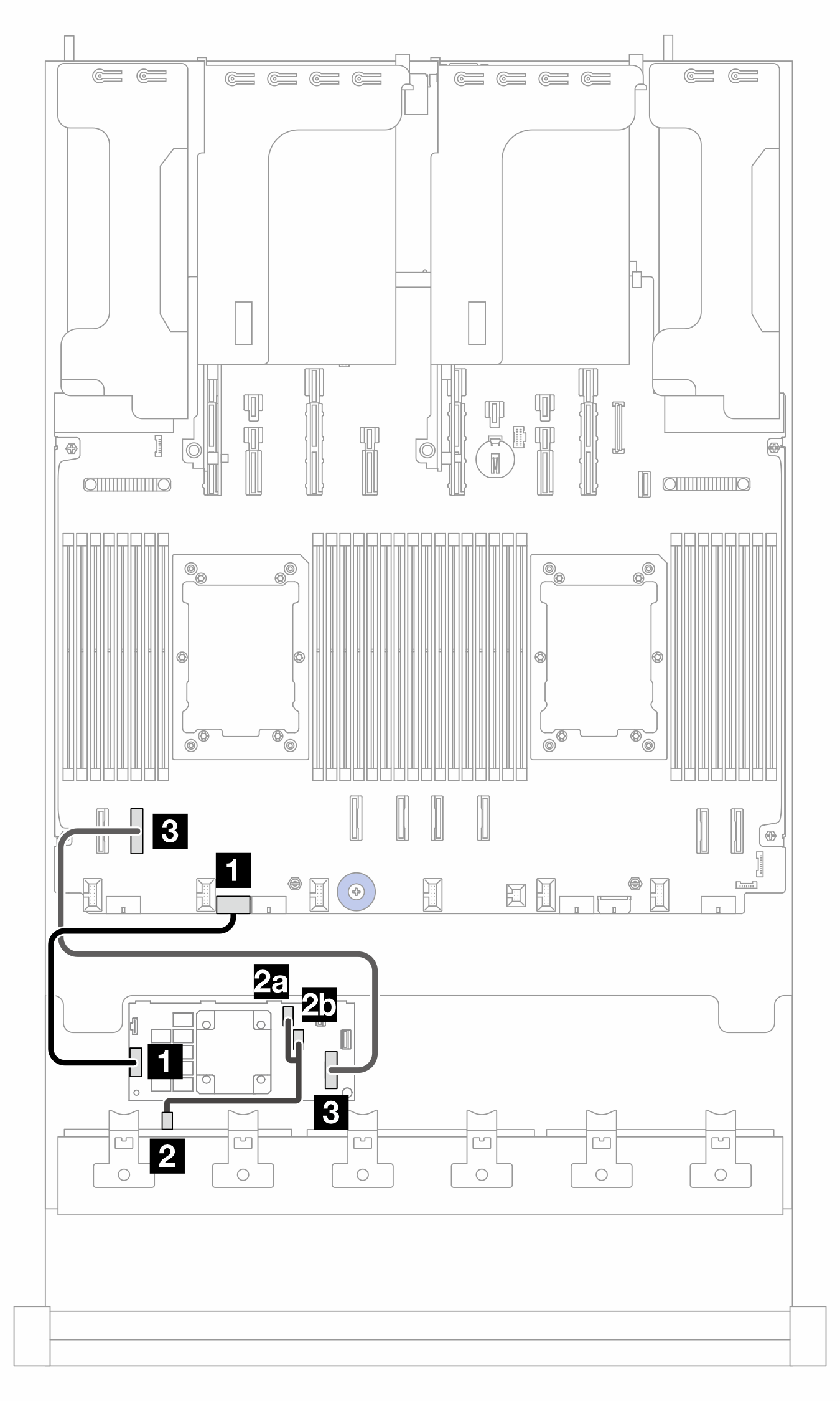 | Figure 5. Cable routing when one processor is installed 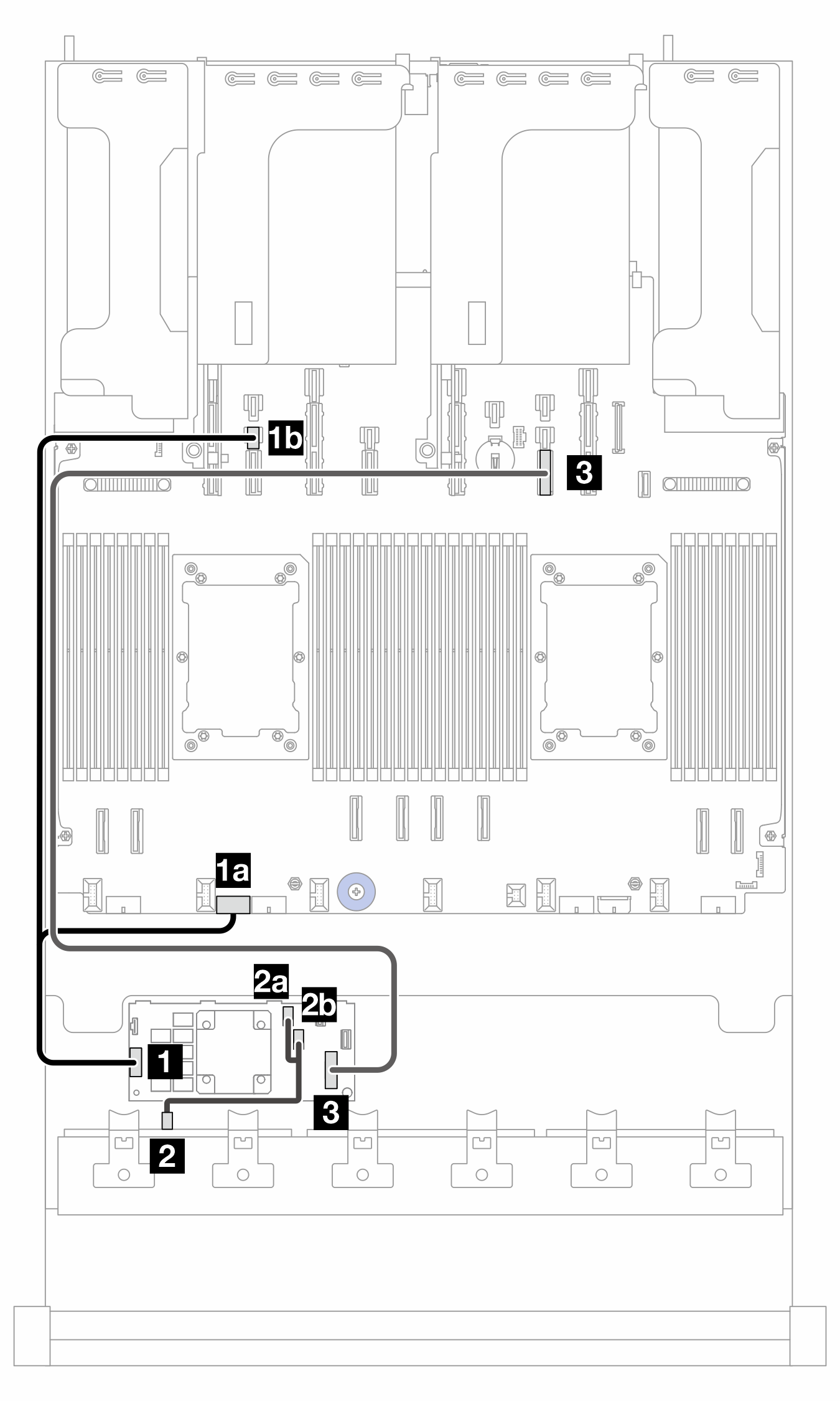 |
PB: processor board; 2P: two processors; 1P: one processor
| From (CFF 16i adapter) | To | Cable length | |
|---|---|---|---|
| 2P | 1P | ||
| 1 POWER | 1 PB: RAID PWR | 1a PB: RAID PWR |
|
| 1b PB: PWR 14 | |||
| 2a C0 | 2 BP1: SAS | 2 BP1: SAS |
|
| 2b C1 | |||
| 3 MB (CFF INPUT) | 3 PB: PCIe 7 | 3 PB: PCIe 10 |
|
NVMe cable routing (config. 4)
Figure 6. Cable routing when two processors are installed  | Figure 7. Cable routing when one processor is installed 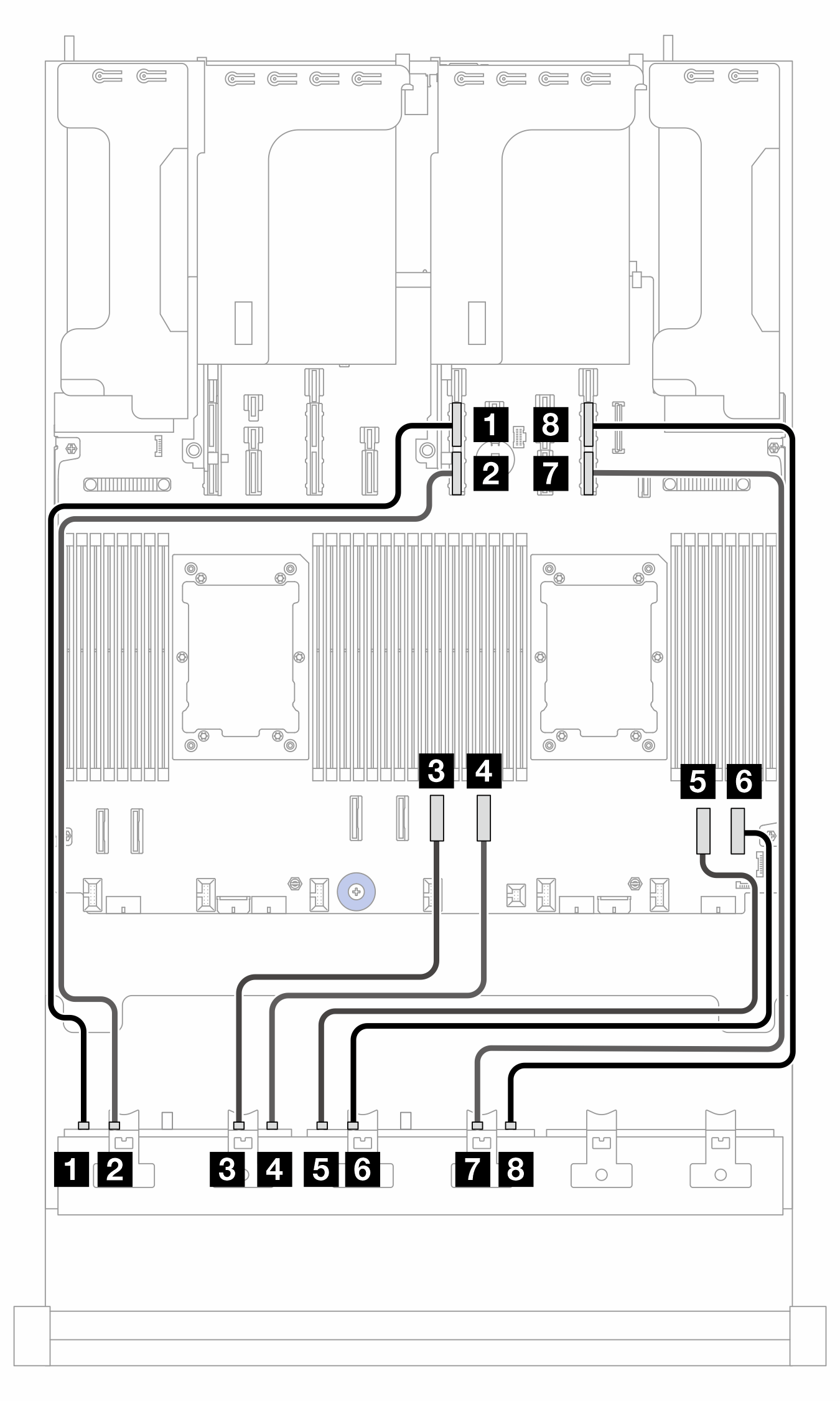 |
2P: two processors; 1P: one processor
| From | To (processor board) | Cable length | |
|---|---|---|---|
| 2P | 1P | ||
| 1 BP1: NVMe 0-1 | 1 PCIe 8 | 1 PCIe 11A |
|
| 2 BP1: NVMe 2-3 | 2 PCIe 7 | 2 PCIe 11B |
|
| 3 BP1: NVMe 4-5 | 3 PCIe 6 | 3 PCIe 4 |
|
| 4 BP1: NVMe 6-7 | 4 PCIe 5 | 4 PCIe 3 |
|
| 5 BP2: NVMe 0-1 | 5 PCIe 4 | 5 PCIe 2 |
|
| 6 BP2: NVMe 2-3 | 6 PCIe 3 | 6 PCIe 1 |
|
| 7 BP2: NVMe 4-5 | 7 PCIe 2 | 7 PCIe 9B |
|
| 8 BP2: NVMe 6-7 | 8 PCIe 1 | 8 PCIe 9A |
|
NVMe cable routing (config. 5)
Figure 8. Cable routing to BP1 when slots 5 and 8 are occupied 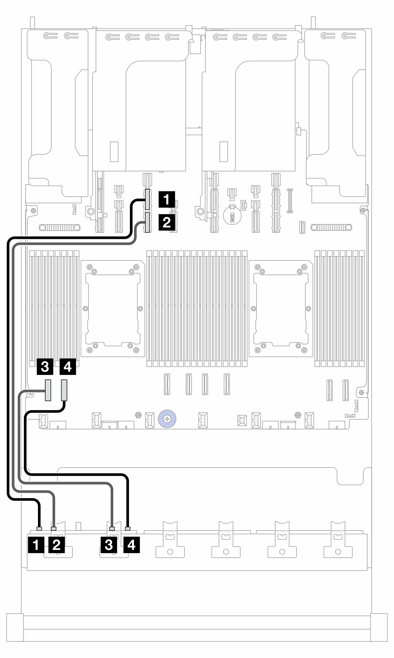 | Figure 9. Cable routing to BP1 when slots 5 and 8 are empty 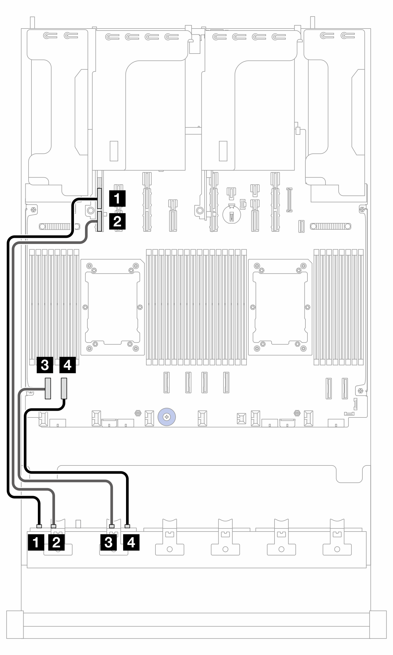 |
| From (BP1) | To (processor board) | Cable length | |
|---|---|---|---|
| slot 5/8 occupied | slot 5/8 empty | ||
| 1 NVMe 0-1 | 1 PCIe 13A | 1 PCIe 15A | 600 mm |
| 2 NVMe 2-3 | 2 PCIe 13B | 2 PCIe 15B | 600 mm |
| 3 NVMe 4-5 | 3 PCIe 8 | 3 PCIe 8 | 350 mm |
| 4 NVMe 6-7 | 4 PCIe 7 | 4 PCIe 7 | 350 mm |
Figure 10. Cable routing to BP2
| From (BP2) | To (processor board) | Cable length |
|---|---|---|
| 1 NVMe 0-1 | 1 PCIe 6 | 250 mm |
| 2 NVMe 2-3 | 2 PCIe 5 | 250 mm |
| 3 NVMe 4-5 | 3 PCIe 4 | 250 mm |
| 4 NVMe 6-7 | 4 PCIe 3 | 250 mm |
Figure 11. Cable routing to BP3 when slots 5 and 8 are occupied 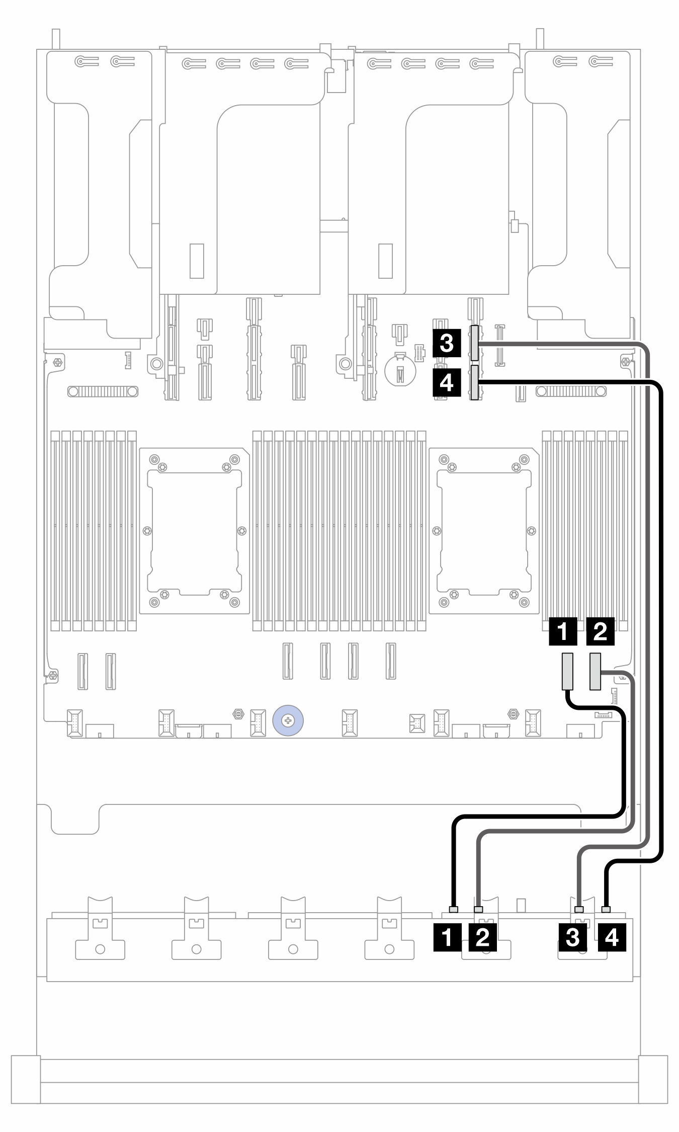 | Figure 12. Cable routing to BP3 when slots 5 and 8 are empty 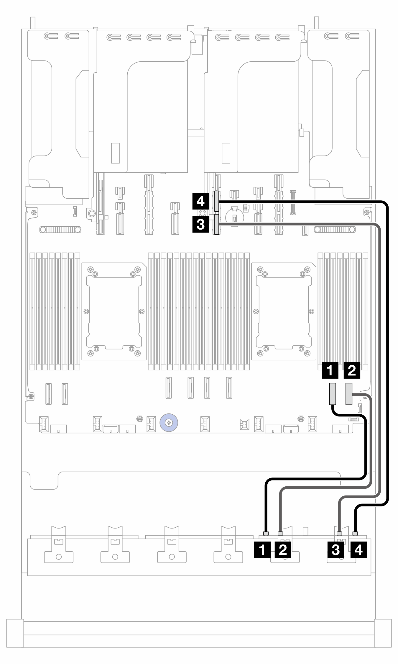 |
| From (BP3) | To (processor board) | Cable length | |
|---|---|---|---|
| slot 5/8 occupied | slot 5/8 empty | ||
| 1 NVMe 0-1 | 1 PCIe 2 | 1 PCIe 2 | 350 mm |
| 2 NVMe 2-3 | 2 PCIe 1 | 2 PCIe 1 | 350 mm |
| 3 NVMe 4-5 | 3 PCIe 9A | 3 PCIe 11B | 600 mm |
| 4 NVMe 6-7 | 4 PCIe 9B | 4 PCIe 11A | 600 mm |
Give documentation feedback