8 x 2.5" SAS/SATA + 8 x 2.5" AnyBay/NVMe
This topic provides cable routing information for the 8 x 2.5" SAS/SATA + 8 x 2.5" AnyBay/NVMe configuration.
The configuration numbers in the table below are for descriptive purposes only.
| BP config. | Storage controller | Config. No. |
|---|---|---|
| 8 x 2.5" SAS/SATA + 8 x 2.5" AnyBay (BP1 + BP2) | 2 x SFF 8i | 1 |
| 1 x SFF 16i | 2 | |
| 1 x CFF 16i | 3 | |
| 8 x 2.5" SAS/SATA + 8 x 2.5" NVMe (BP1 + BP2) | 1 x SFF 8i/16i | 4 |
| 1 x CFF 16i | 5 |
NVMe cable routing (config. 1/2/3/4/5)
Figure 1. NVMe cable routing to BP2 when two processors are installed 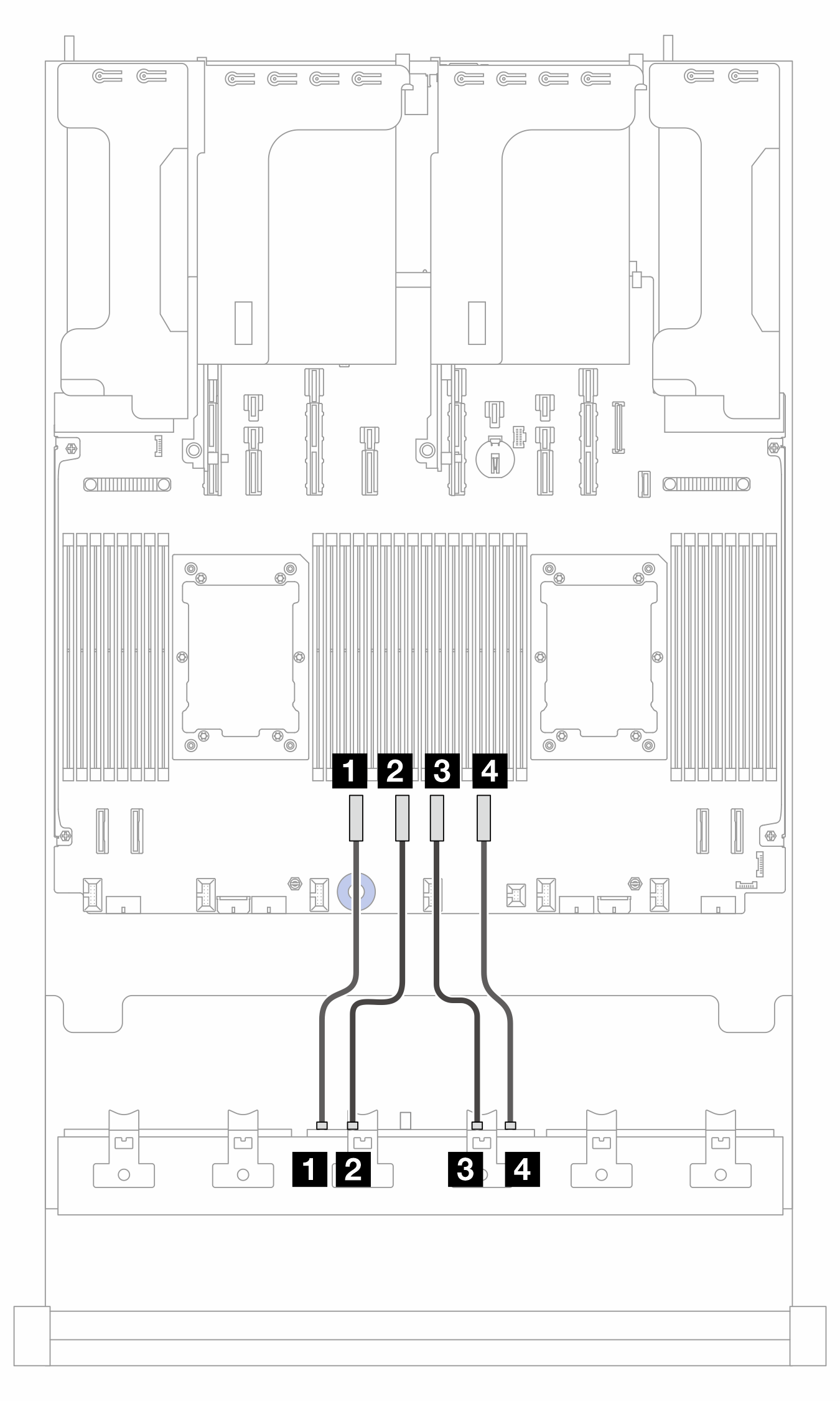 | Figure 2. NVMe cable routing to BP2 when one processor is installed 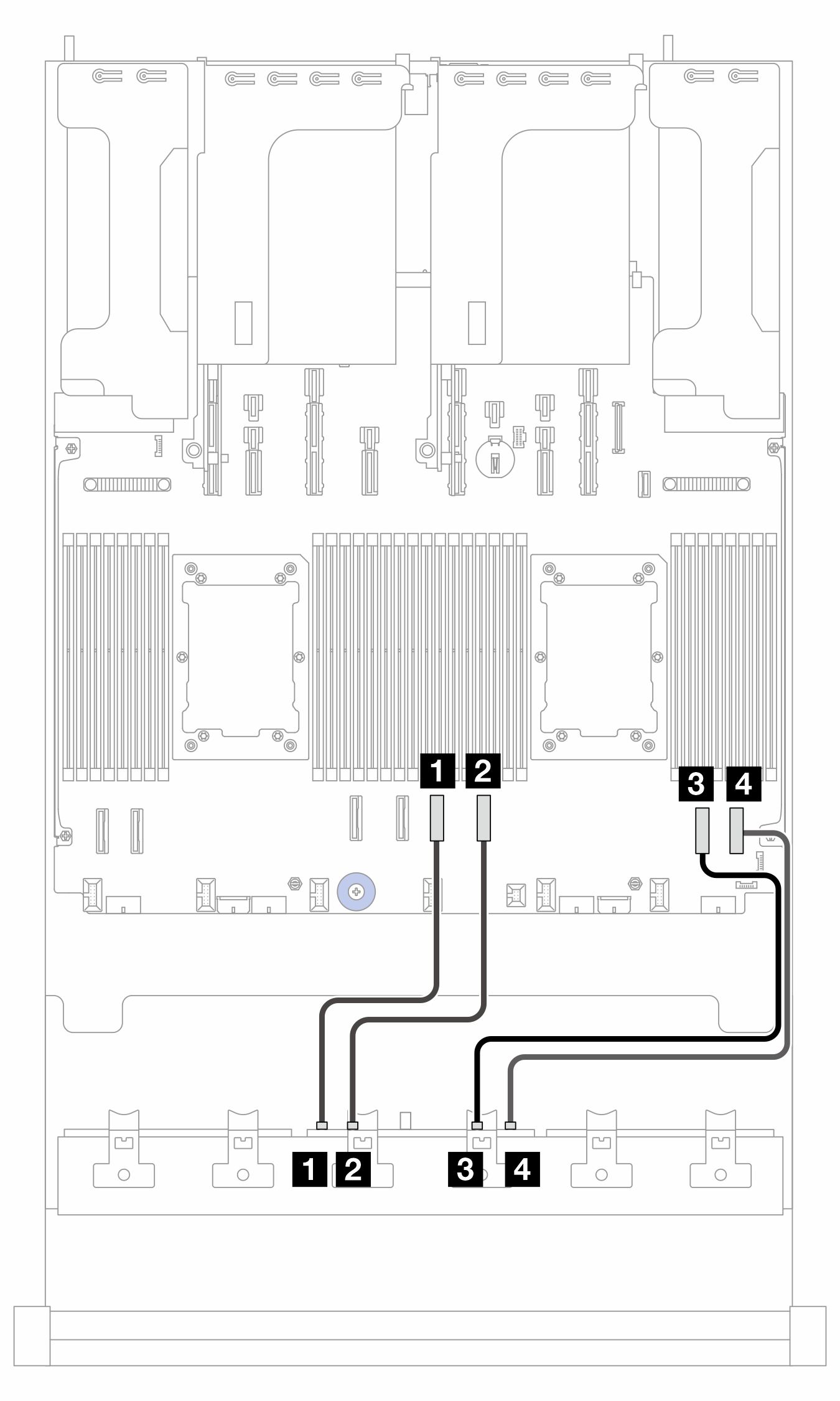 |
2P: two processors; 1P: one processor
| From (BP2) | To (processor board) | Cable length | |
|---|---|---|---|
| 2P | 1P | ||
| 1 NVMe 0-1 | 1 PCIe 6 | 1 PCIe 4 |
|
| 2 NVMe 2-3 | 2 PCIe 5 | 2 PCIe 3 |
|
| 3 NVMe 4-5 | 3 PCIe 4 | 3 PCIe 2 |
|
| 4 NVMe 6-7 | 4 PCIe 3 | 4 PCIe 1 |
|
Cable routing to SFF 8i/16i adapter (config. 1/2/4)
Note
The location of the adapter and cable connectors on the adapter may differ from those shown in the illustration. For details, see the table below.
Cable 2 is not needed in config. 4.
Figure 3. Cable routing to SFF 8i/16i adapter

| From | To | Cable length | |
|---|---|---|---|
| 1 BP1: SAS | 1 8i adapter:
| 1 16i adapter:
| 900 mm |
| 2 BP2: SAS | 2 8i adapter:
| 2
| 900 mm |
Cable routing to CFF 16i adapter (config. 3/5)
Note
Cable 3 is not needed in config. 5.
Figure 4. Cable routing when two processors are installed 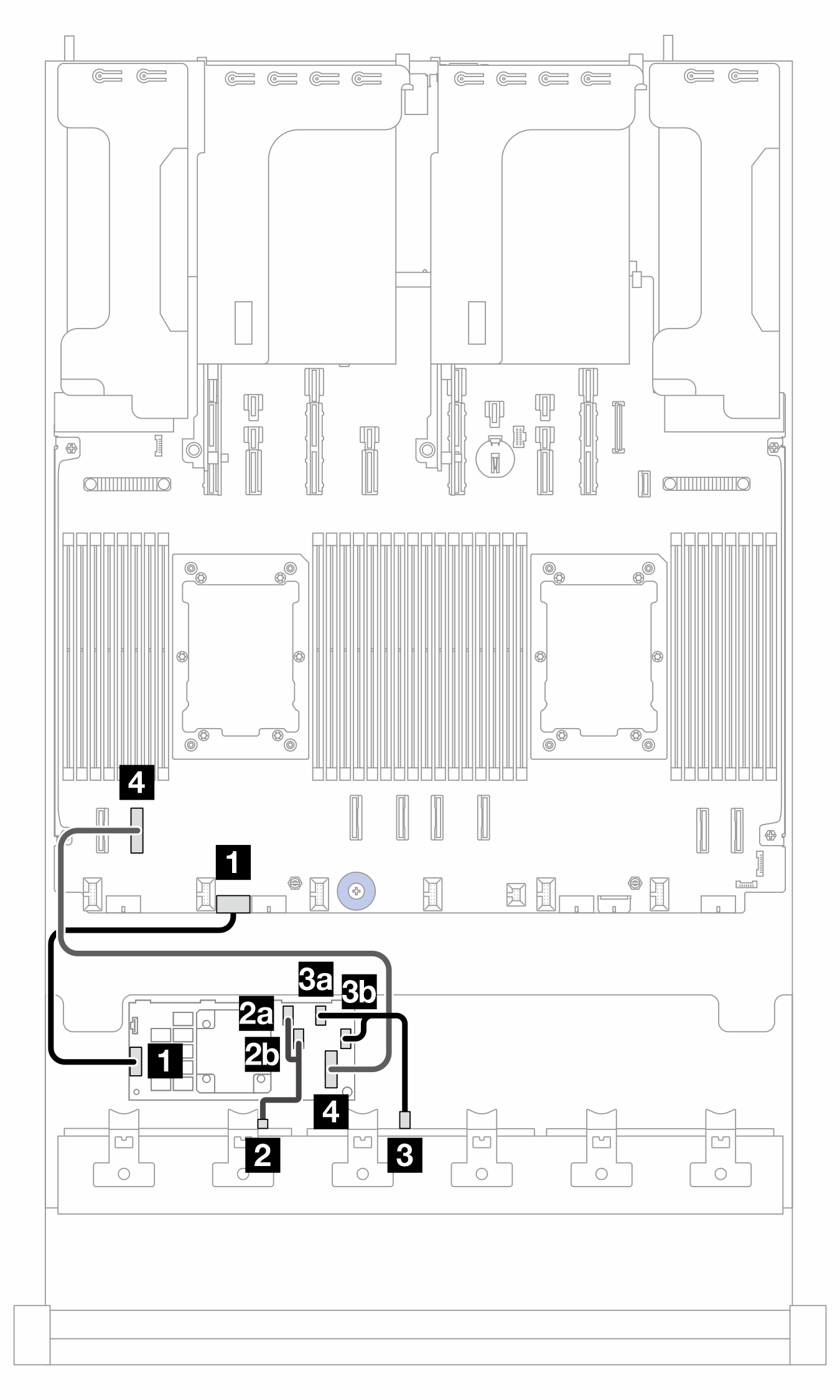 | Figure 5. Cable routing when one processor is installed 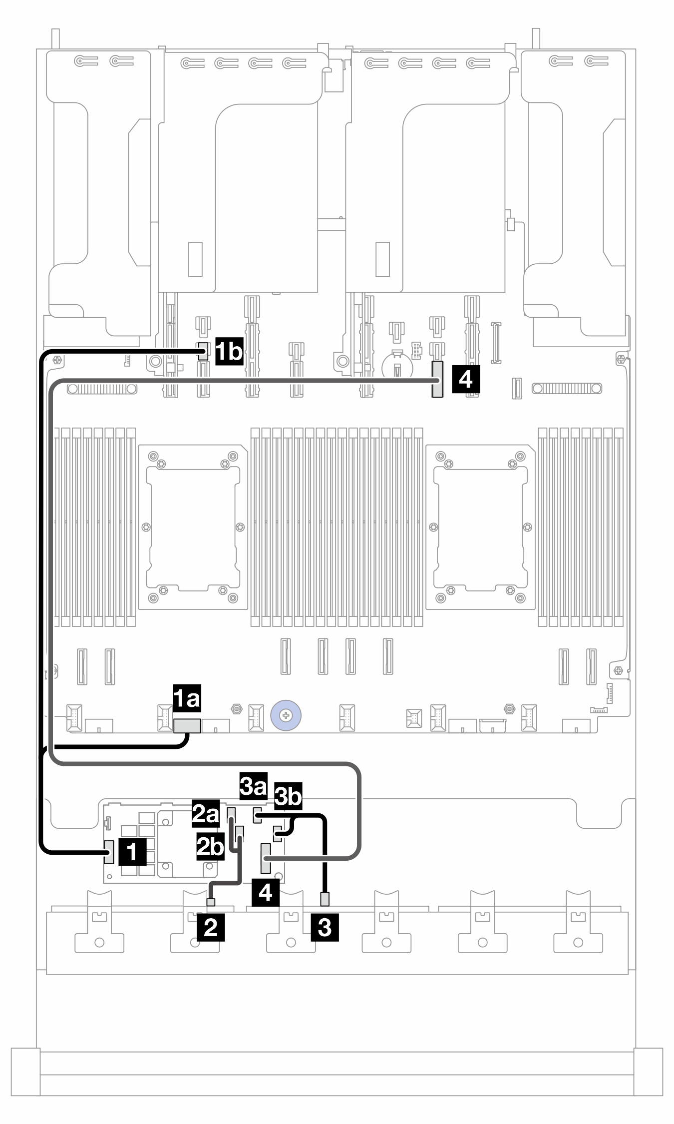 |
2P: two processors; 1P: one processor; PB: processor board
| From (CFF 16i adapter) | To | Cable length | |
|---|---|---|---|
| 2P | 1P | ||
| 1 POWER | 1 PB: RAID PWR | 1a PB: RAID PWR |
|
| 1b PB: PWR 14 | |||
| 2a C0 | 2 BP1: SAS | 2 BP1: SAS |
|
| 2b C1 | |||
| 3a C2 | 3 BP2: SAS | 3 BP2: SAS |
|
| 3b C3 | |||
| 4 MB (CFF INPUT) | 4 PB: PCIe 7 | 4 PB: PCIe 10 |
|
Give documentation feedback