8/16/24 x 2,5-Zoll-AnyBay/NVMe
Dieser Abschnitt enthält Informationen zur Kabelführung für eine Konfiguration mit 8 x 2,5-Zoll-/16 x 2,5-Zoll-/24 x 2,5-Zoll-AnyBay/NVMe.
Die Konfigurationsnummern in der folgenden Tabelle dienen lediglich beschreibenden Zwecken.
| BP-Konfig. | Speichercontroller | Konfig. Nr. |
|---|---|---|
| 8 x 2,5-Zoll-NVMe (BP1) | – | 1 |
| 8 x 2,5-Zoll-AnyBay (BP1) | 1 x SFF 8i/16i | 2 |
| 1 x CFF 16i | 3 | |
| 16 x 2,5-Zoll-NVMe (BP1 + BP2) | – | 4 |
| 24 x 2,5-Zoll-NVMe (BP1 + BP2 + BP3) | – | 5 |
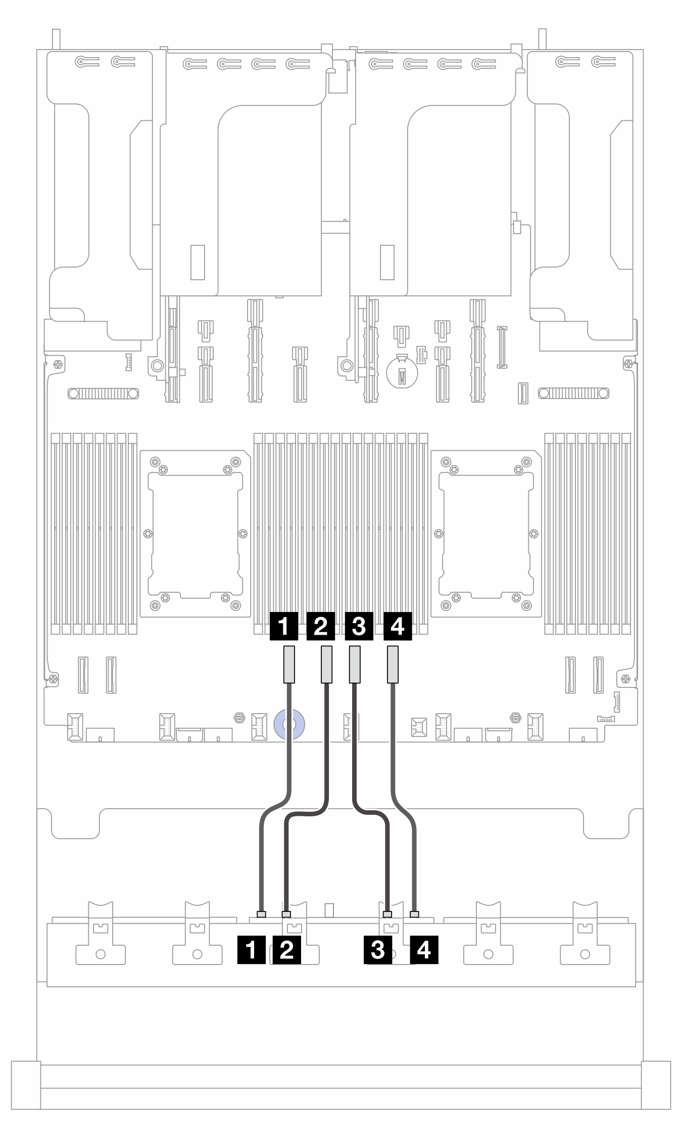
NVMe-Kabelführung (Konfiguration 1/2/3)
Abbildung 1. Kabelführung bei zwei installierten Prozessoren 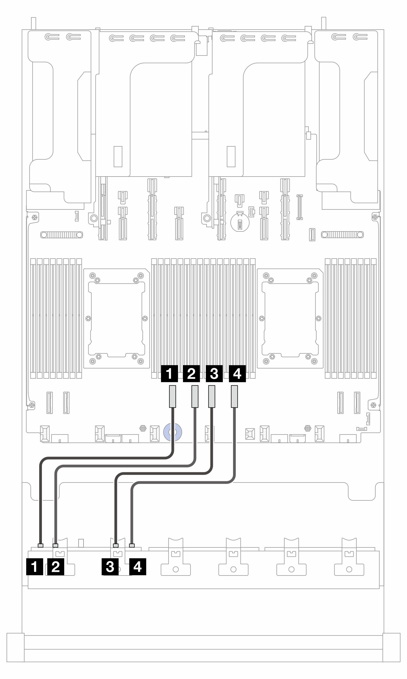 | Abbildung 2. Kabelführung bei einem installierten Prozessor 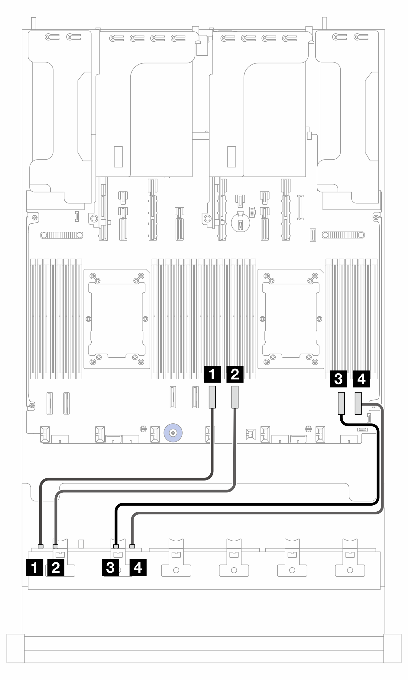 |
2P: zwei Prozessoren; 1P: ein Prozessor
| Von (BP1) | Zu (Prozessorplatine) | Kabellänge | |
|---|---|---|---|
| 2P | 1P | ||
| 1 NVMe 0-1 | 1 PCIe 6 | 1 PCIe 4 |
|
| 2 NVMe 2-3 | 2 PCIe 5 | 2 PCIe 3 |
|
| 3 NVMe 4–5 | 3 PCIe 4 | 3 PCIe 2 |
|
| 4 NVMe 6-7 | 4 PCIe 3 | 4 PCIe 1 |
|
Kabelführung zum SFF 8i/16i Adapter (Konfig. 2)
Anmerkung
Die Position der Adapter- und Kabelanschlüsse am Adapter kann von der Abbildung abweichen. Weitere Informationen finden Sie in der folgenden Tabelle.
Abbildung 3. Kabelführung zum SFF 8i/16i Adapter
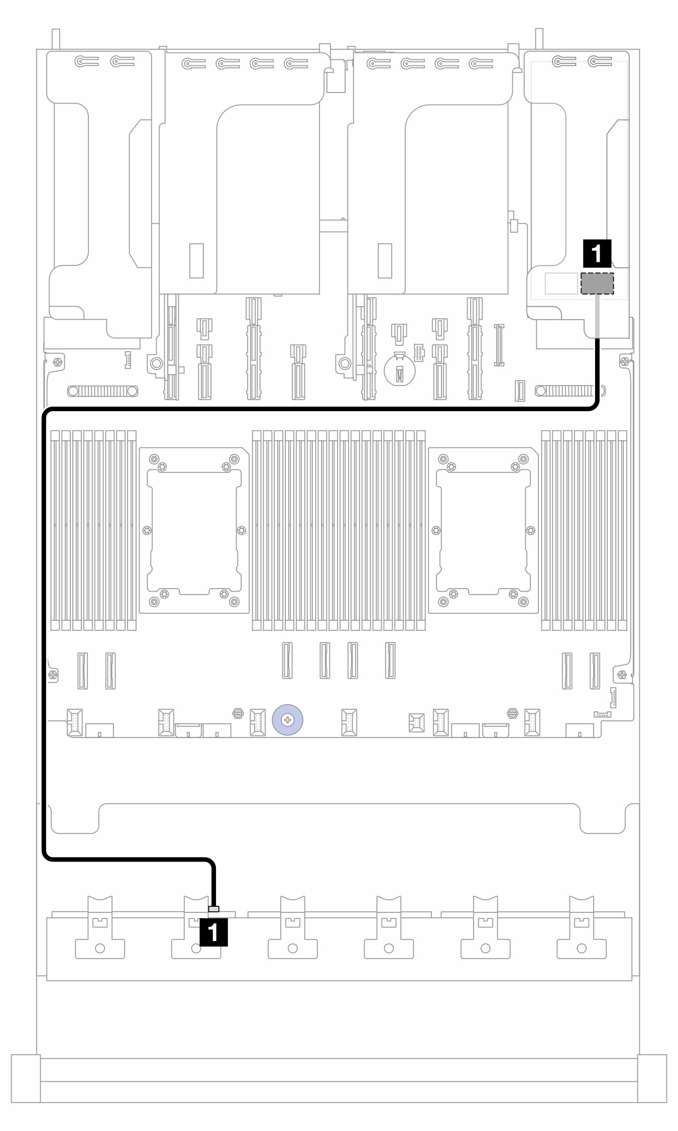
| Von | Zu | Kabellänge |
|---|---|---|
| 1 BP1: SAS | 1 8i/16i Adapter:
| 900 mm |
Kabelführung zum CFF 16i Adapter (Konfig. 3)
Abbildung 4. Kabelführung bei zwei installierten Prozessoren 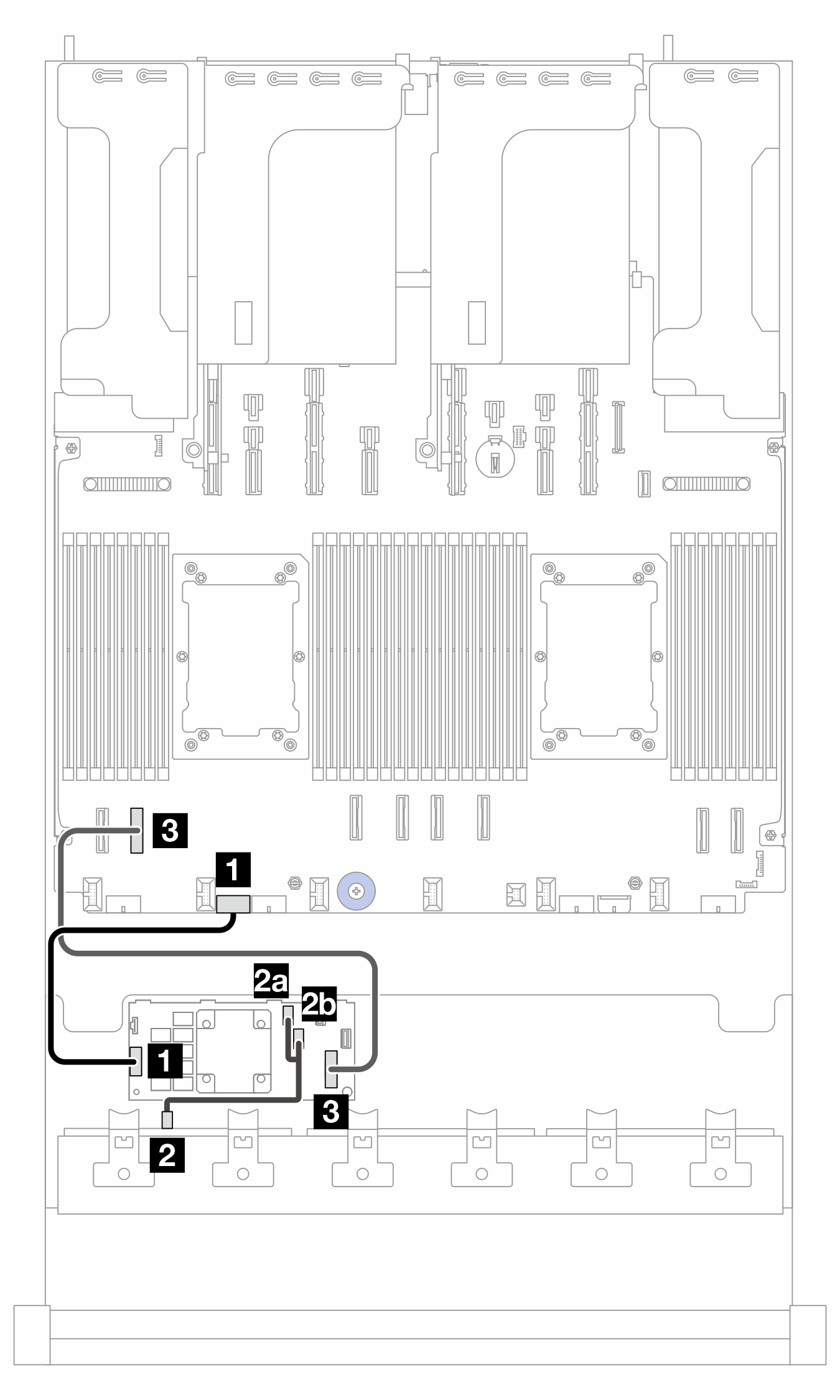 | Abbildung 5. Kabelführung bei einem installierten Prozessor 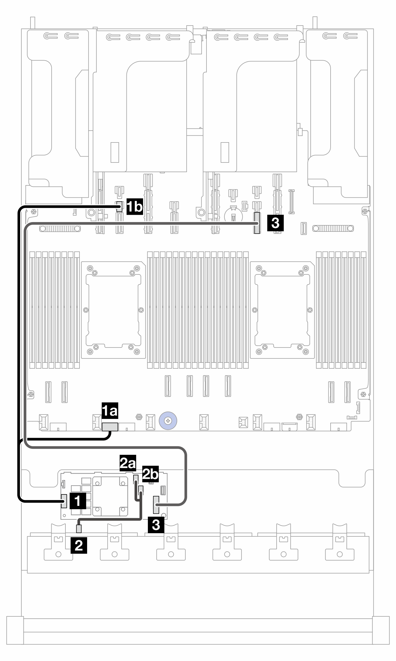 |
PB: Prozessorplatine; 2P: zwei Prozessoren; 1P: ein Prozessor
| Von (CFF 16i Adapter) | Zu | Kabellänge | |
|---|---|---|---|
| 2P | 1P | ||
| 1 POWER | 1 PB: RAID PWR | 1a PB: RAID PWR |
|
| 1b PB: PWR 14 | |||
| 2a C0 | 2 BP1: SAS | 2 BP1: SAS |
|
| 2b C1 | |||
| 3 MB (CFF INPUT) | 3 PB: PCIe 7 | 3 PB: PCIe 10 |
|
NVMe-Kabelführung (Konfiguration 4)
Abbildung 6. Kabelführung bei zwei installierten Prozessoren 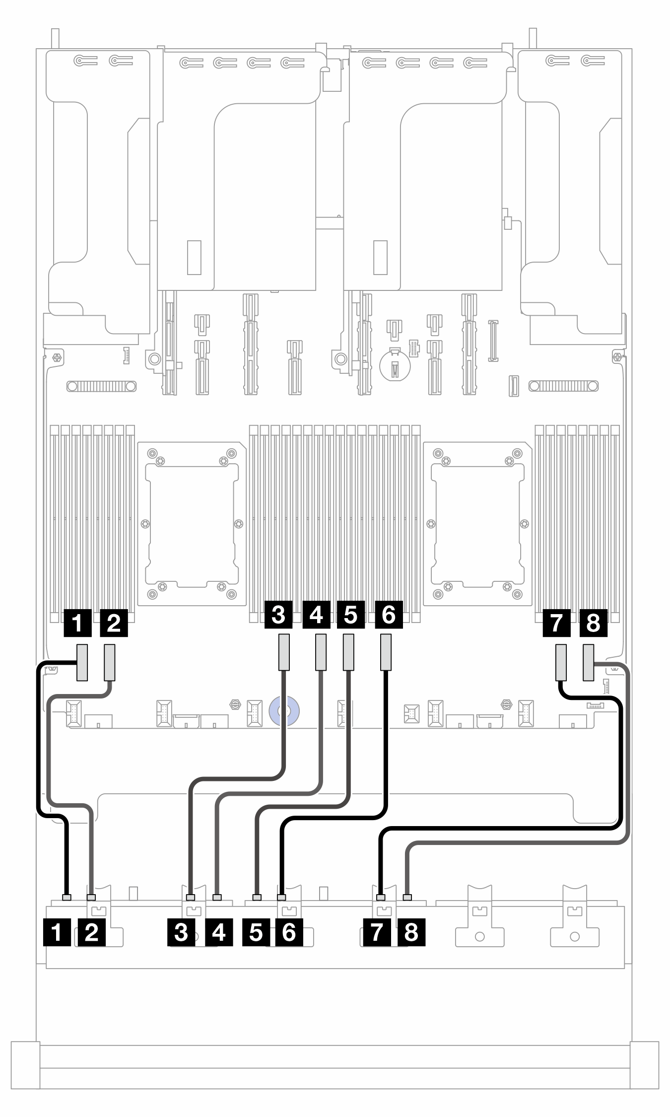 | Abbildung 7. Kabelführung bei einem installierten Prozessor 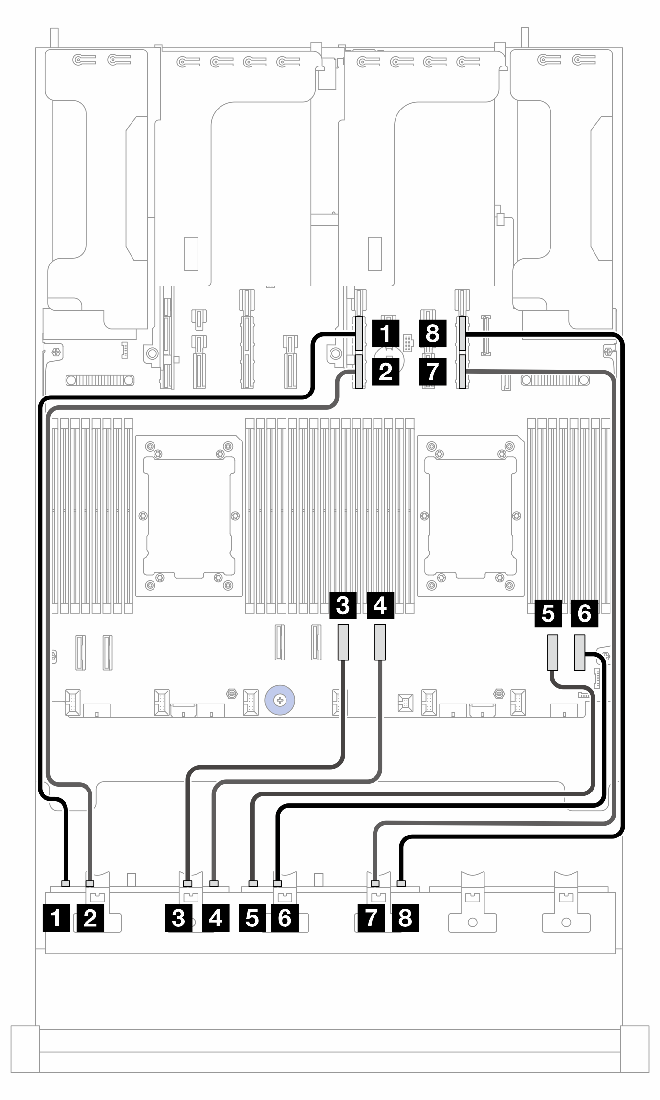 |
2P: zwei Prozessoren; 1P: ein Prozessor
| Von | Zu (Prozessorplatine) | Kabellänge | |
|---|---|---|---|
| 2P | 1P | ||
| 1 BP1: NVMe 0-1 | 1 PCIe 8 | 1 PCIe 11A |
|
| 2 BP1: NVMe 2-3 | 2 PCIe 7 | 2 PCIe 11B |
|
| 3 BP1: NVMe 4-5 | 3 PCIe 6 | 3 PCIe 4 |
|
| 4 BP1: NVMe 6-7 | 4 PCIe 5 | 4 PCIe 3 |
|
| 5 BP2: NVMe 0-1 | 5 PCIe 4 | 5 PCIe 2 |
|
| 6 BP2: NVMe 2-3 | 6 PCIe 3 | 6 PCIe 1 |
|
| 7 BP2: NVMe 4-5 | 7 PCIe 2 | 7 PCIe 9B |
|
| 8 BP2: NVMe 6-7 | 8 PCIe 1 | 8 PCIe 9A |
|
NVMe-Kabelführung (Konfiguration 5)
Abbildung 8. Kabelführung zu BP1 bei Belegung der Steckplätze 5 und 8 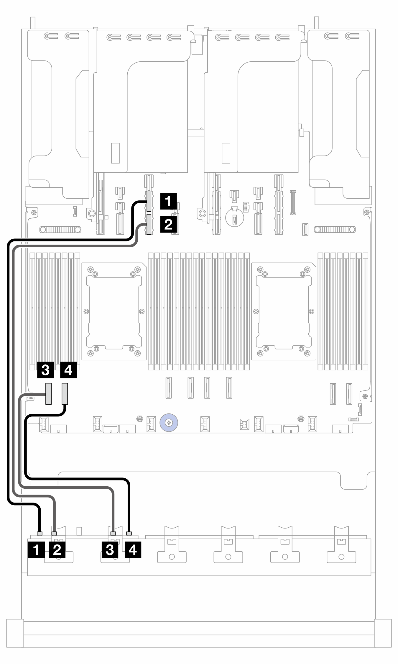 | Abbildung 9. Kabelführung zu BP1, wenn Steckplätze 5 und 8 leer sind 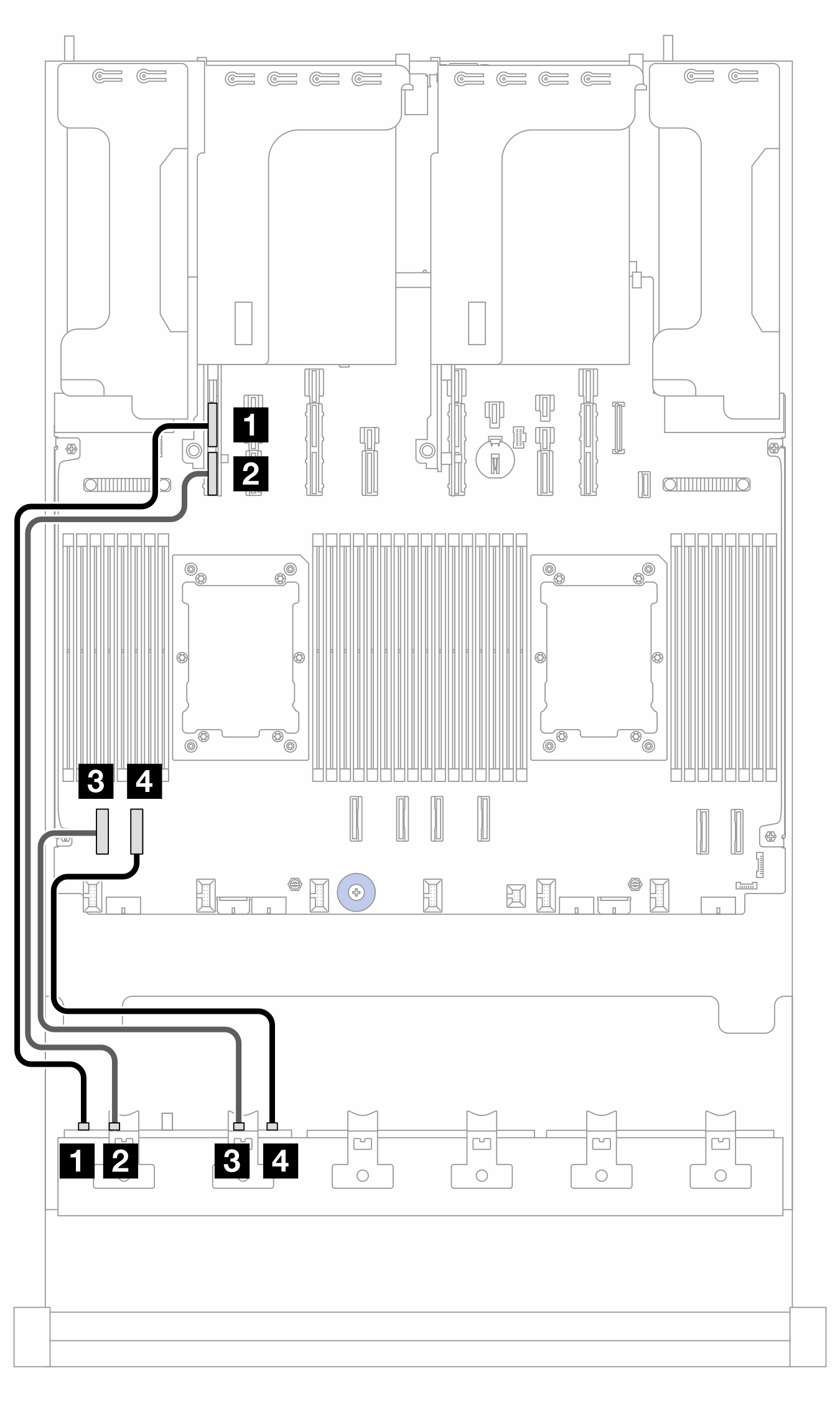 |
| Von (BP1) | Zu (Prozessorplatine) | Kabellänge | |
|---|---|---|---|
| Steckplatz 5/8 belegt | Steckplatz 5/8 leer | ||
| 1 NVMe 0-1 | 1 PCIe 13A | 1 PCIe 15A | 600 mm |
| 2 NVMe 2-3 | 2 PCIe 13B | 2 PCIe 15B | 600 mm |
| 3 NVMe 4–5 | 3 PCIe 8 | 3 PCIe 8 | 350 mm |
| 4 NVMe 6-7 | 4 PCIe 7 | 4 PCIe 7 | 350 mm |
Abbildung 10. Kabelführung zu BP2
| Von (BP2) | Zu (Prozessorplatine) | Kabellänge |
|---|---|---|
| 1 NVMe 0-1 | 1 PCIe 6 | 250 mm |
| 2 NVMe 2-3 | 2 PCIe 5 | 250 mm |
| 3 NVMe 4–5 | 3 PCIe 4 | 250 mm |
| 4 NVMe 6-7 | 4 PCIe 3 | 250 mm |
Abbildung 11. Kabelführung zu BP3 bei Belegung der Steckplätze 5 und 8 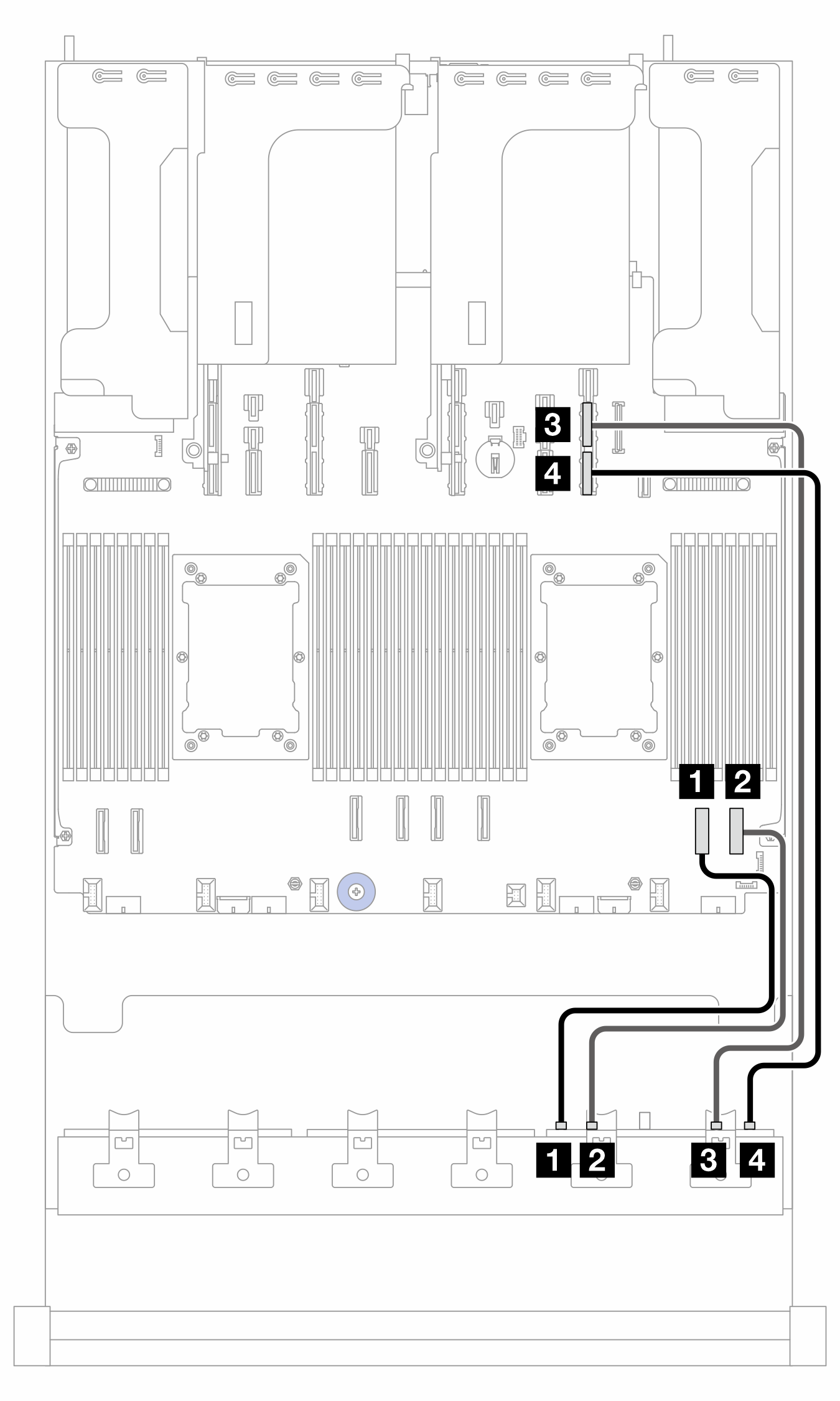 | Abbildung 12. Kabelführung zu BP3, wenn Steckplätze 5 und 8 leer sind 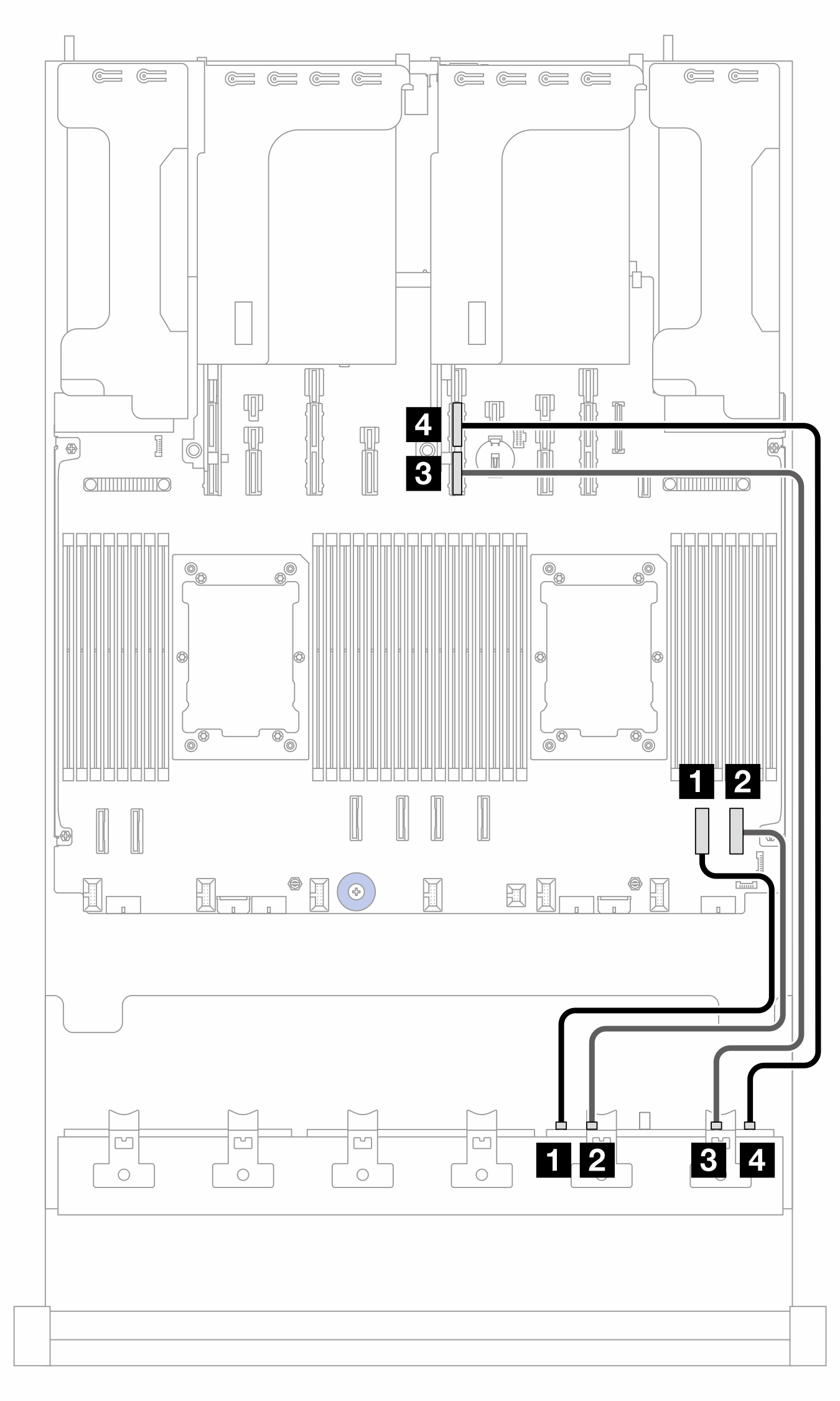 |
| Von (BP3) | Zu (Prozessorplatine) | Kabellänge | |
|---|---|---|---|
| Steckplatz 5/8 belegt | Steckplatz 5/8 leer | ||
| 1 NVMe 0-1 | 1 PCIe 2 | 1 PCIe 2 | 350 mm |
| 2 NVMe 2-3 | 2 PCIe 1 | 2 PCIe 1 | 350 mm |
| 3 NVMe 4–5 | 3 PCIe 9A | 3 PCIe 11B | 600 mm |
| 4 NVMe 6-7 | 4 PCIe 9B | 4 PCIe 11A | 600 mm |
Feedback geben