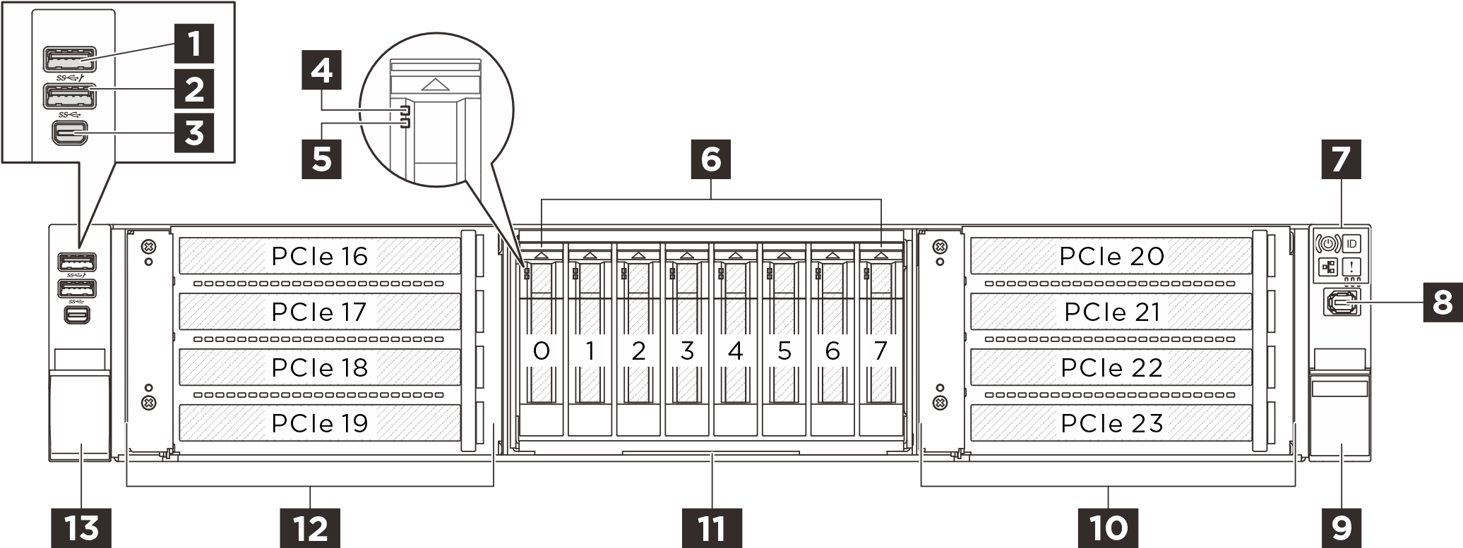
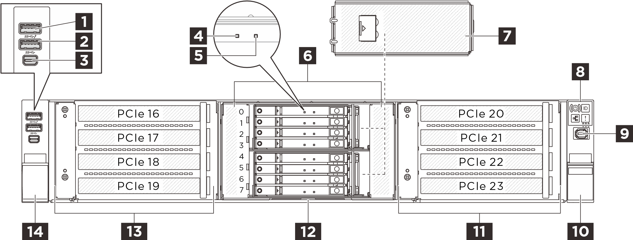
Front view
This section contains information about the controls, LEDs, and connectors on the front of the server.
Front view of 2.5-inch drive configuration
Front view of E3.S drive configuration
Front view of E3.S and M.2 drive configuration
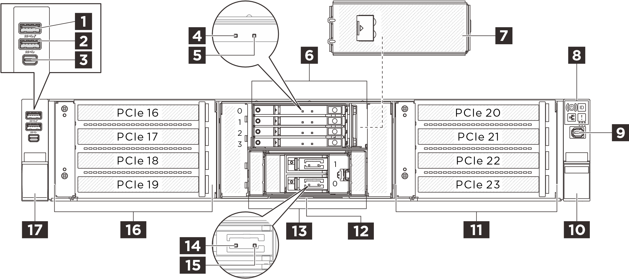
Front components overview
USB 3.2 Gen 1 (5Gbps) connector with USB 2.0 XCC system management
The connector can function as a regular USB 3.2 Gen 1 connector to the host OS; it can be used to attach a USB-compatible device, such as a USB keyboard, USB mouse, or USB storage device.
In addition, the connector can function as a USB 2.0 Lenovo XClarity Controller management port.
USB 3.2 Gen 1 (5Gbps) connector
The connector can be used to attach a USB-compatible device, such as a USB keyboard, USB mouse, or USB storage device.
Mini DisplayPort connector
The Mini DisplayPort (MiniDP) connector can be used to attach a high-performance monitor and a direct-drive monitor with a video converter, or the devices that use a MiniDP connector. The maximum video resolution is 1920 x 1200 at 60 Hz.
Drive activity LED (green)
The drive bays are designed for hot-swap drives. The number of the installed drives in your server varies by model. When you install drives, follow the order of the drive bay numbers.
Drive status LED (yellow)
The LED is lit: the drive has failed.
The LED is flashing slowly (once per second): the drive is being rebuilt.
The LED is flashing rapidly (three times per second): the drive is being identified.
Drive bays
The drive bays are designed for hot-swap drives. The number of the installed drives in your server varies by model. When you install drives, follow the order of the drive bay numbers.
Front operator panel
For more information about the front operator panel, see Front-operator-panel LEDs and buttons.
E3.S drive cage cover
The E3.S drive cage cover of each E3.S drive cage is designed for proper EMI integrity of the server. The server models with E3.S drives should always operate with the E3.S drive cage cover installed for every E3.S drive cage.
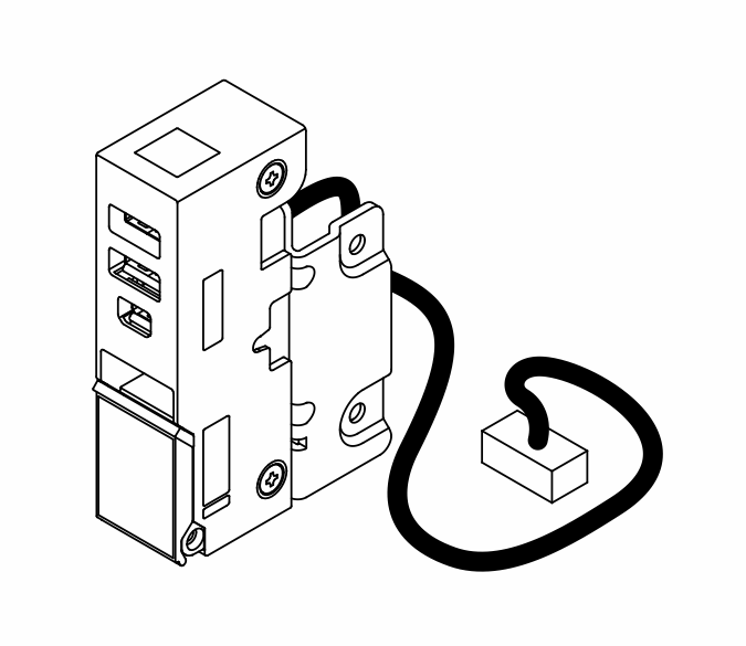
External diagnostics connector
The connector is for connecting an external diagnostics handset. For more about its functions, see External Diagnostics Handset.
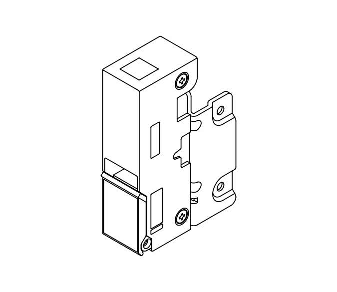
Rack latches
If your server is installed in a rack, you can use the rack latches to help you slide the server out of the rack. You also can use the rack latches and screws to secure the server in the rack so that the server cannot slide out, especially in vibration-prone areas.
| The server supports one of the following left rack latch: | Right rack latch (with front operator panel) | |
| Standard left rack latch | Left rack latch with USB/MiniDP | |
 |  |  |
Pull-out information tab
The Lenovo XClarity Controller network access label is attached on the pull-out information tab. The default Lenovo XClarity Controller hostname and the IPv6 Link Local Address (LLA) are provided on the tab.
For more information, see Set the network connection for the Lenovo XClarity Controller.
PCIe riser assemblies
The server supports two PCIe riser assemblies on the front. For more information, see PCIe slots and PCIe adapters.