Remove an SXM5 GPU
Follow instructions in this section to remove an SXM5 GPU. The procedure must be executed by a trained technician.
About this task
Attention
- Read Installation Guidelines and Safety inspection checklist to ensure that you work safely.
- Power off the server and peripheral devices and disconnect the power cords and all external cables. See Power off the server.
- If the server is installed in a rack, slide the server out on its rack slide rails to gain access to the top cover, or remove the server from the rack. See Remove the server from rack.
- A torque screwdriver is available for request if you do not have one at hand.
Note
Make sure you have the required tools listed below available to properly replace the component:
- Phillips #1 bit
- Torx T15 bit
- Manual torque screwdriver
- DIMM tool
- Alcohol cleaning pad
- SXM5 PCM Kit
- SR675 V3 water loop putty pad kit
- SR675 V3 water loop service kit
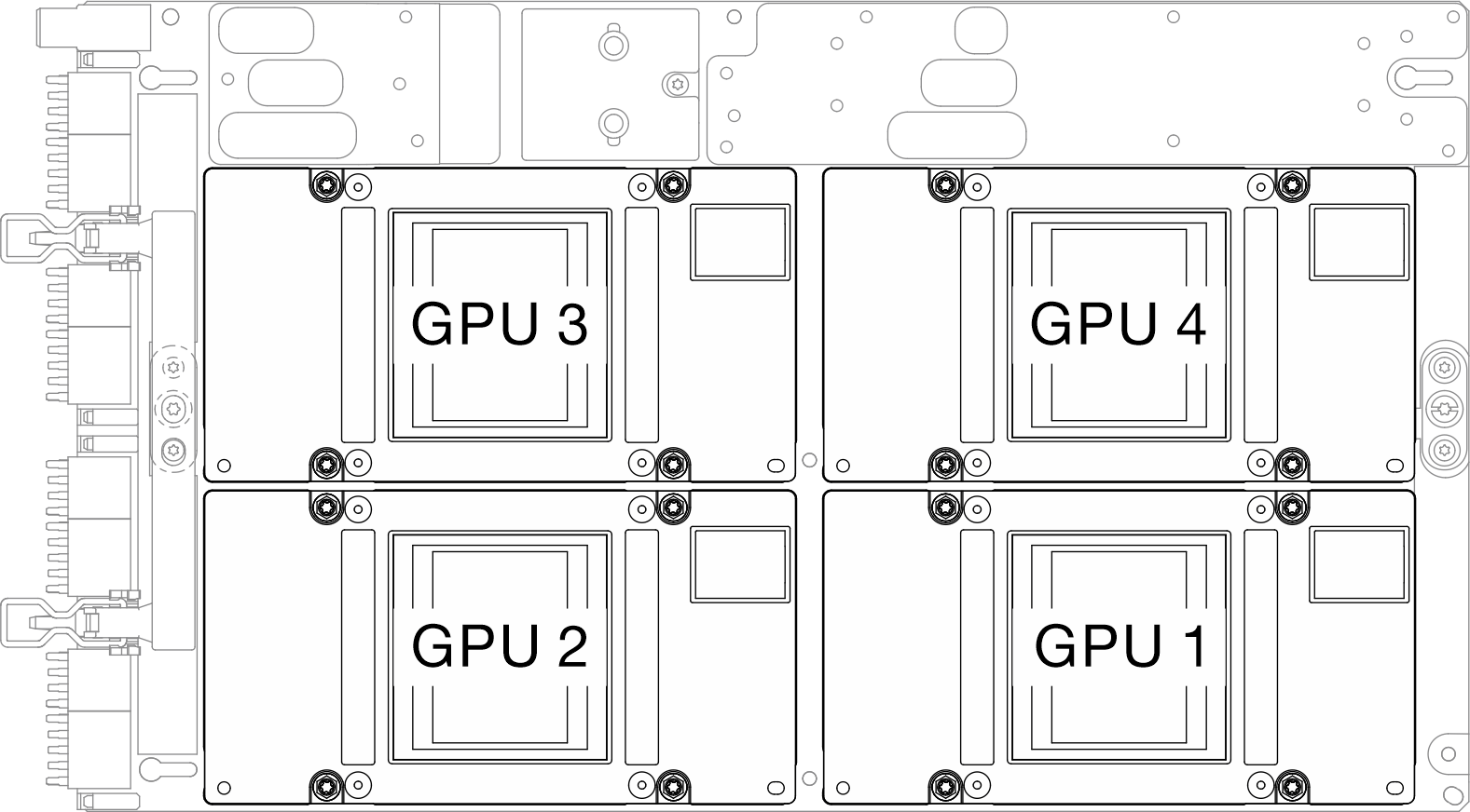
The following illustration shows the SXM5 GPU numbering.
Figure 1. SXM5 GPU numbering
Procedure
- Make preparation for this task.
- Unfasten the two cable ties on the front drive tray to release the cables.Figure 2. Unfastening the cable ties
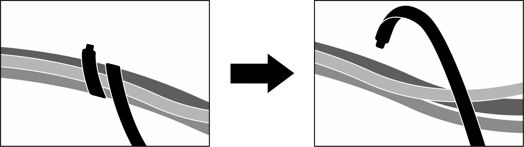
- Unfasten the two cable ties on the front drive tray to release the cables.
- Locate the SXM5 GPU to be removed.
- Remove the SXM5 GPU.


 Unfasten the four Torx T15 screws in the sequence shown in the illustration below.NoteLoosen or tighten the screws with a torque screwdriver set to the proper torque. For reference, the torque required for the screws to be fully loosen or tighten is 0.45-0.56 newton-meters, 4.0-5.0 inch-pounds.
 Carefully remove the SXM5 GPU out of the SXM5 GPU board.Figure 3. SXM5 GPU removal
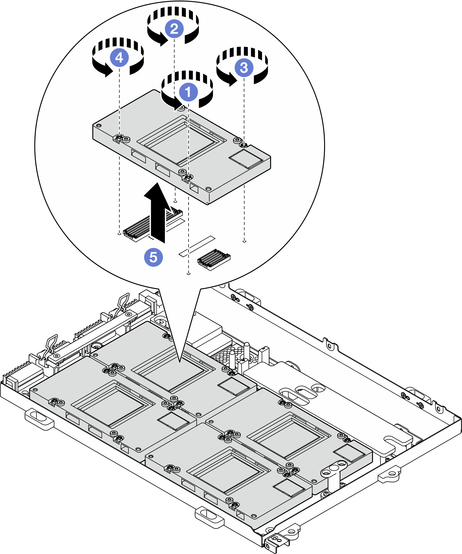
After you finish
If you are instructed to return the component or optional device, follow all packaging instructions, and use any packaging materials for shipping that are supplied to you.
Demo video
Give documentation feedback