Install the GPU complex adapter plate
Follow instructions in this section to install the GPU complex adapter plate. The procedure must be executed by a trained technician.
About this task
Attention
- Read Installation Guidelines and Safety inspection checklist to ensure that you work safely.
- Touch the static-protective package that contains the component to any unpainted metal surface on the server; then, remove it from the package and place it on a static-protective surface.
- Two people and one lifting device on site that can support up to 400 lb (181 kg) are required to perform this procedure. If you do not already have a lifting device available, Lenovo offers the Genie Lift GL-8 material lift that can be purchased at Data Center Solution Configurator. Make sure to include the Foot-release brake and the Load Platform when ordering the Genie Lift GL-8 material lift.
Note
Make sure you have the required tools listed below available to properly replace the component:
- Torque screwdriver which can be set to 0.6 newton-meters, 5.3 inch-pounds
- Torx T15 extended bit (200 mm long)
Note
The GPU complex adapter plate might look different from the illustration.
Procedure
- Align the GPU complex adapter plate with the four guide pins in the bottom of the 8U GPU shuttle; then, lower the GPU complex adapter plate into the 8U GPU shuttle.Figure 1. GPU complex adapter plate installation
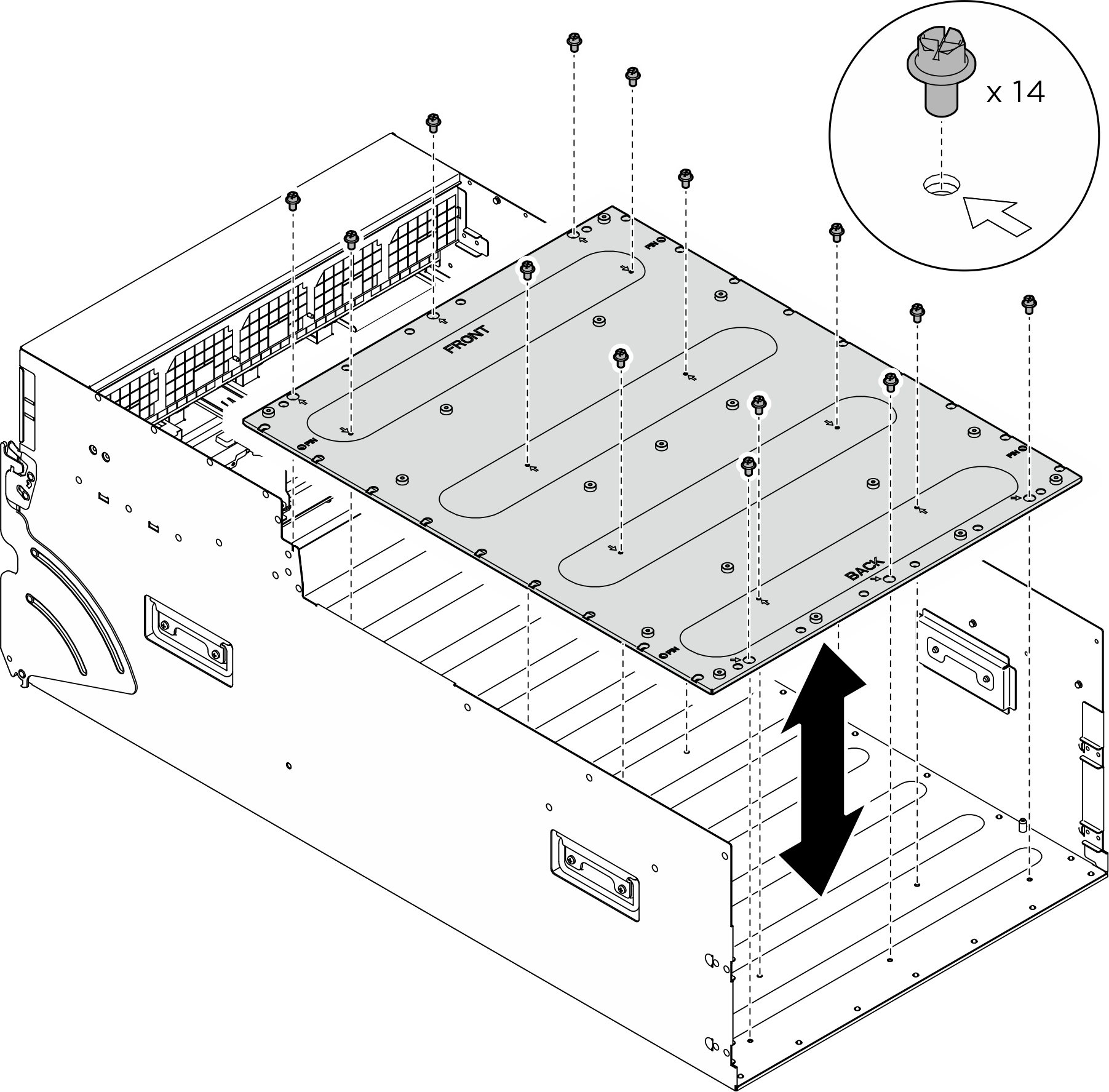
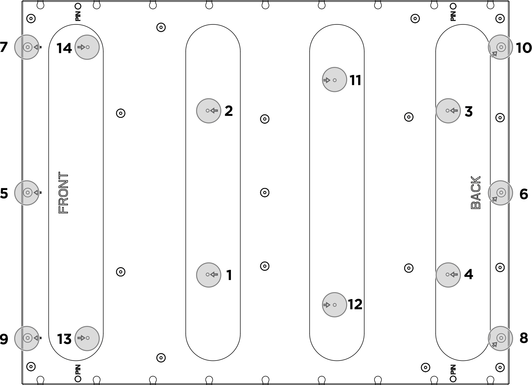
- Locate the fourteen screw holes marked with an arrow; then, follow the sequence shown in the illustration below to fasten the fourteen screws to secure the GPU complex adapter plate.Figure 2. Screw tightening sequence
- Flip over the front PCIe switch cable harness.
- Flip over the front PCIe switch cable harness, and make sure that it correctly engages the four guide pins on the 8U GPU shuttle.
- Locate the ten screw holes marked with C on both sides of the 8U GPU shuttle; then, fasten the ten screws to secure the front PCIe switch cable harness.
Figure 3. Flipping over the front PCIe switch cable harness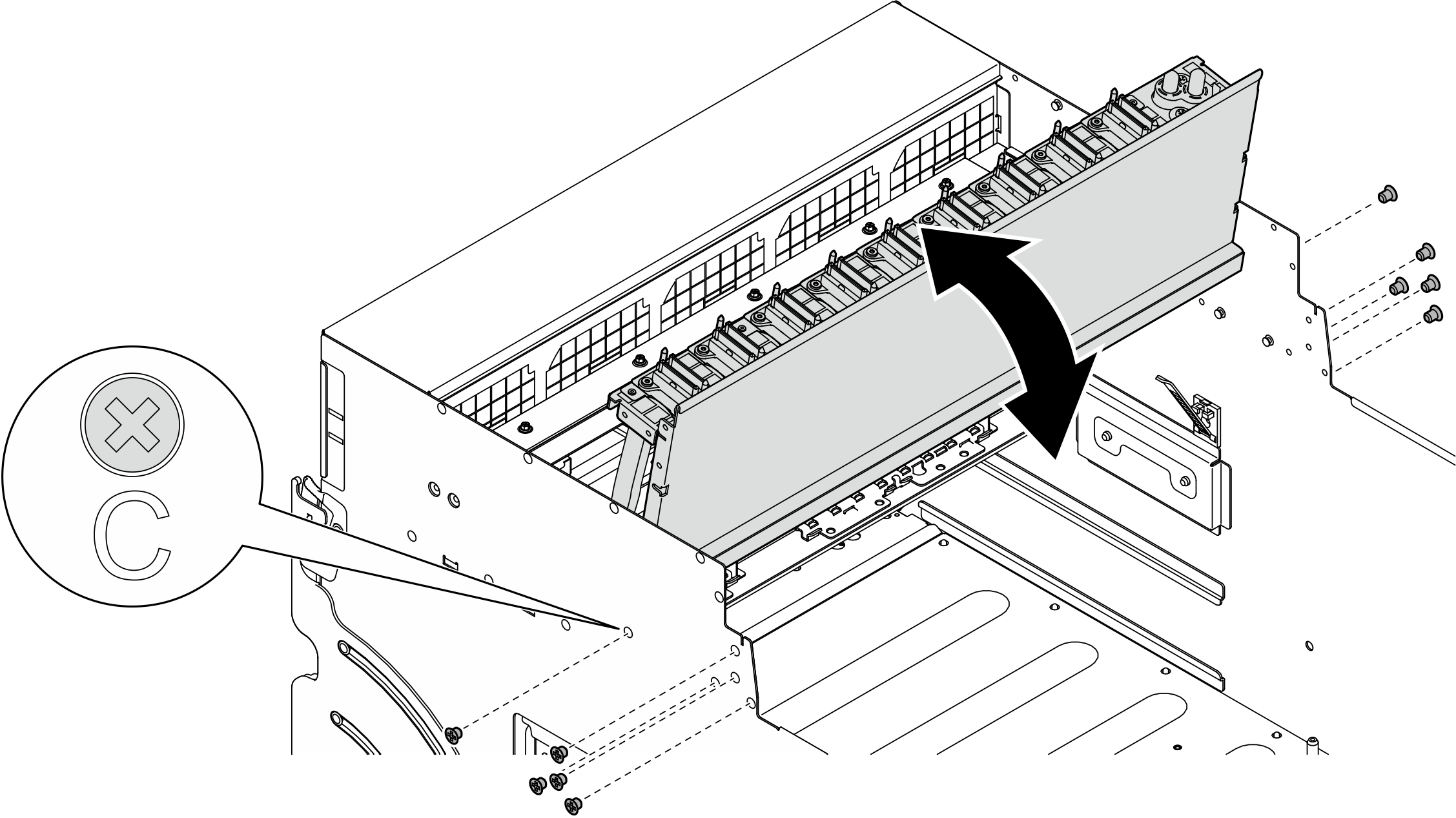
- Install the PCIe switch shuttle.
 Press the two blue release latches.
 Press the two lock latches on both sides of the PCIe switch shuttle.
 Push the PCIe switch shuttle into the 8U GPU shuttle until it stops.
 Rotate the two release levers until they lock into place.Figure 4. PCIe switch shuttle installation to 8U GPU shuttle
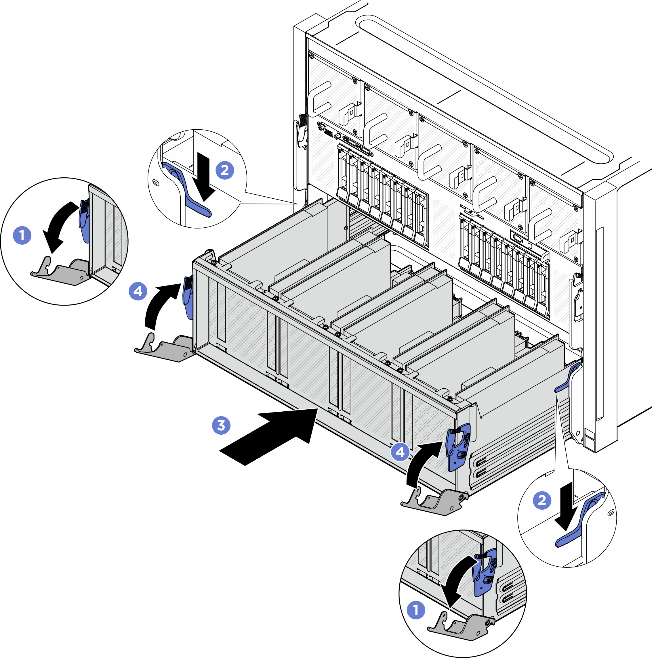
After you finish
- Reinstall all the GPU air ducts. Depending on the configuration, see Install an H100/H200 GPU air duct or Install an MI300X GPU air duct.
- Reinstall all the rear fan control board assemblies. See Install a rear fan control board assembly.
- If necessary, reinstall the rear support bracket.
- Hold the rear support bracket in the correct orientation as illustrated, and slide it into the 8U GPU shuttle.
- Locate the four screw holes marked with A on both sides of the 8U GPU shuttle; then, fasten the four screws to secure the rear support bracket.
Figure 5. Rear support bracket installation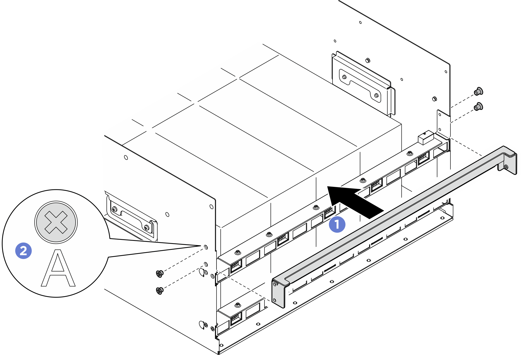
- Reinstall the power complex. See Install the power complex.
- Reinstall the cable cover. See Install the cable cover.
- Reinstall the 8U GPU shuttle. See Install the 8U GPU shuttle.
- Reinstall all the 2.5-inch hot-swap drives or drive bay fillers (if any) into the drive bays. See Install a 2.5-inch hot-swap drive
- Reinstall all the front fans. See Install a hot-swap fan (front and rear).
- Reinstall all the power supply units. See Install a hot-swap power supply unit.
- Complete the parts replacement. See Complete the parts replacement.
Give documentation feedback