Install the system I/O board
Follow the instructions in this section to install the system I/O board, also known as Datacenter Secure Control Module (DC-SCM).
About this task
Read Installation Guidelines and Safety inspection checklist to ensure that you work safely.
Power off the server and peripheral devices and disconnect the power cords and all external cables. See Power off the server.
Prevent exposure to static electricity, which might lead to system halt and loss of data, by keeping static-sensitive components in their static-protective packages until installation, and handling these devices with an electrostatic-discharge wrist strap or other grounding system.
Go to Drivers and Software download website for ThinkSystem SR850 V4 to see the latest firmware and driver updates for your server.
Go to Update the firmware for more information on firmware updating tools.
Procedure
- Install the system I/O board.
 Align the contacts on the system I/O board with the slots on the processor board, and use both hands to push the system I/O board and slightly insert it into the connector.NoteTo prevent the contacts of the system I/O board from damage, ensure that the system I/O board is aligned correctly with the connector on the processor board, and remains as horizontal as possible during the insertion.
 Install the screws to install the system I/O board to the supporting metal sheet.
Figure 1. System I/O board installation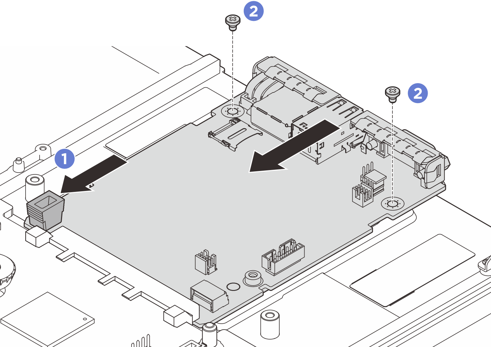
- Install the system board assembly to the server.
- Hold the front lifting handle and the rear plunger on the system board assembly; then, insert the rear end of the system board assembly into the rear of the chassis
- Lower the front end of the system board assembly into the chassis.
 Slide the system board assembly toward the rear of the chassis until it clicks into place. Make sure that the rear connectors on the new system board assembly are inserted into the corresponding holes in the rear panel.
Figure 2. System board assembly installation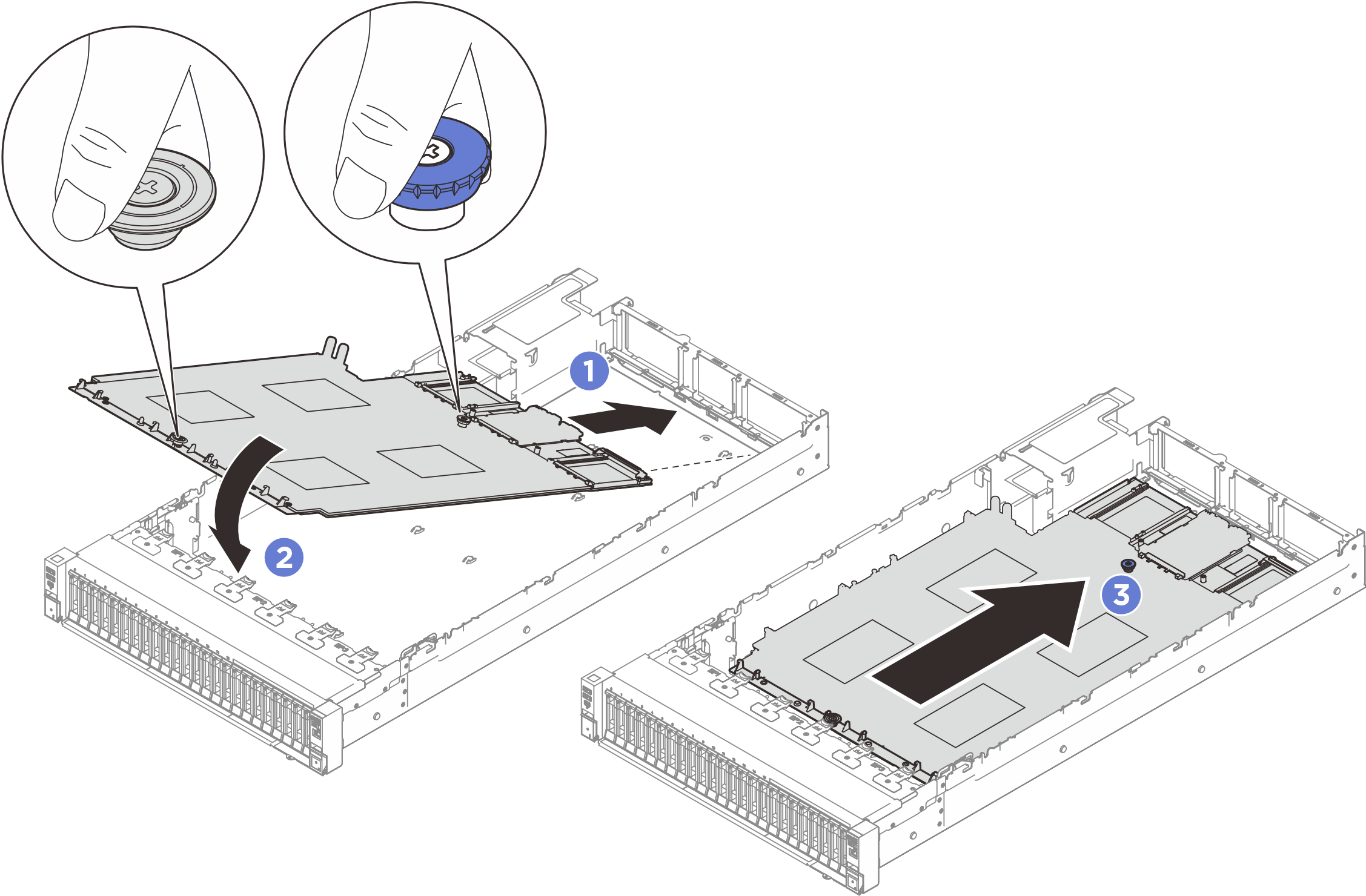
After you finish
- Reconnect all the cables to the system board assembly. See Internal cable routing.
- Install the MicroSD card, see Install the MicroSD card.
- Reinstall the memory modules. See Install a memory module.
- Reinstall the Lenovo Processor Neptune Core Modules. See Install the Lenovo Processor Neptune Core Module.
- Reinstall the PHMs. See Install a processor and heat sink.
- Reinstall the power distribution board. See Install the power distribution board.
- Reinstall the intrusion switch. See Install the intrusion switch.
- Reinstall the rear air baffle. See Install the rear air baffle.
- Reinstall the PCIe risers. See Install a PCIe riser.
- Reinstall the front air baffle. See Install the front air baffle.
- Reinstall the fans and the fan cage assembly. See Install a fan and Install the fan cage.
- Reinstall the rear top cover. See Install the rear top cover.
- Reinstall the front top cover. See Install the front top cover.
- Reinstall the OCP modules if necessary. See Install an OCP module.
- Reinstall the power supply units. See Install a hot-swap power supply unit.
- Ensure that all components have been reassembled correctly and that no tools or loose screws are left inside the server.
- If the server was installed in a rack, reinstall the server into the rack. See Install the server to rails.
- Reconnect the power cords and any cables that you removed.
- Power on the server and any peripheral devices. See Power on the server.
Update the UEFI firmware. (Lenovo service technicians only) See Procedure for replacing System I/O board (DC-SCM) and updating system firmware on V4 system..
- Update the XCC/UEFI/LXPM/SCM FPGA firmware. See Update the firmware
Perform OneCLI commands or XCC actions to restore the UEFI and XCC settings. See OneCLI commands that restore configuration settings or Using XCC to restore the BMC configuration.
Re-install the FoD key.
Set the TPM policy. See Enable TPM.
If hiding TPM or updating TPM firmware is needed, see Hide/observe TPM or Update the TPM firmware
- Optionally, enable Secure Boot. See Enable UEFI Secure Boot.
Demo video