Install the manifold
Use this information to install the manifold.
About this task
- Extended PH2 screwdriver from FRU for screw driver
SMM3 MANI conduction plate gap pad, if installing a new lower manifold
- SMM3 MANI conduction plate , if replacing the MANI conduction plate
The water might cause irritation to the skin and eyes. Avoid direct contact with the lubricant.


Read Installation Guidelines and Safety inspection checklist to ensure that you work safely.
Ensure proper handling procedures are followed when working with any chemically treated water used in the compute rack cooling system. Ensure that material safety data sheets (MSDS) and safety information are provided by the water chemical treatment supplier and that proper personal protective equipment (PPE) is available as recommended by the water chemical treatment supplier. Protective gloves and eyewear may be recommended as a precaution.
- When removing or installing the manifold, hold the manifold by the sections specified in the illustration below.Figure 1. Manifold touching points

- A video of this procedure is available at YouTube.
Procedure
Install the manifolds
- When installing a new lower manifold (blue-labeled hose), install the mani-conductor to it.Note
Check the gap pad on the bottom of the mani-conductor, if it is damaged or detached, replace it with a new one. If installing a new mani-conductor, peel off the plastic film from the gap pad before installation.
Figure 2. Mani-conductor gap pad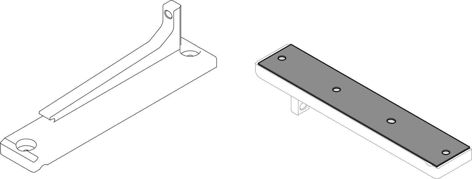
 Align the mani-conductor to the standoffs on the lower manifold; then, install the mani-condutor to the manifold.
 Install two T10 screws to secure the mani-conductor to the lower manifold.
Figure 3. Installing the mani-conductor to a new lower manifold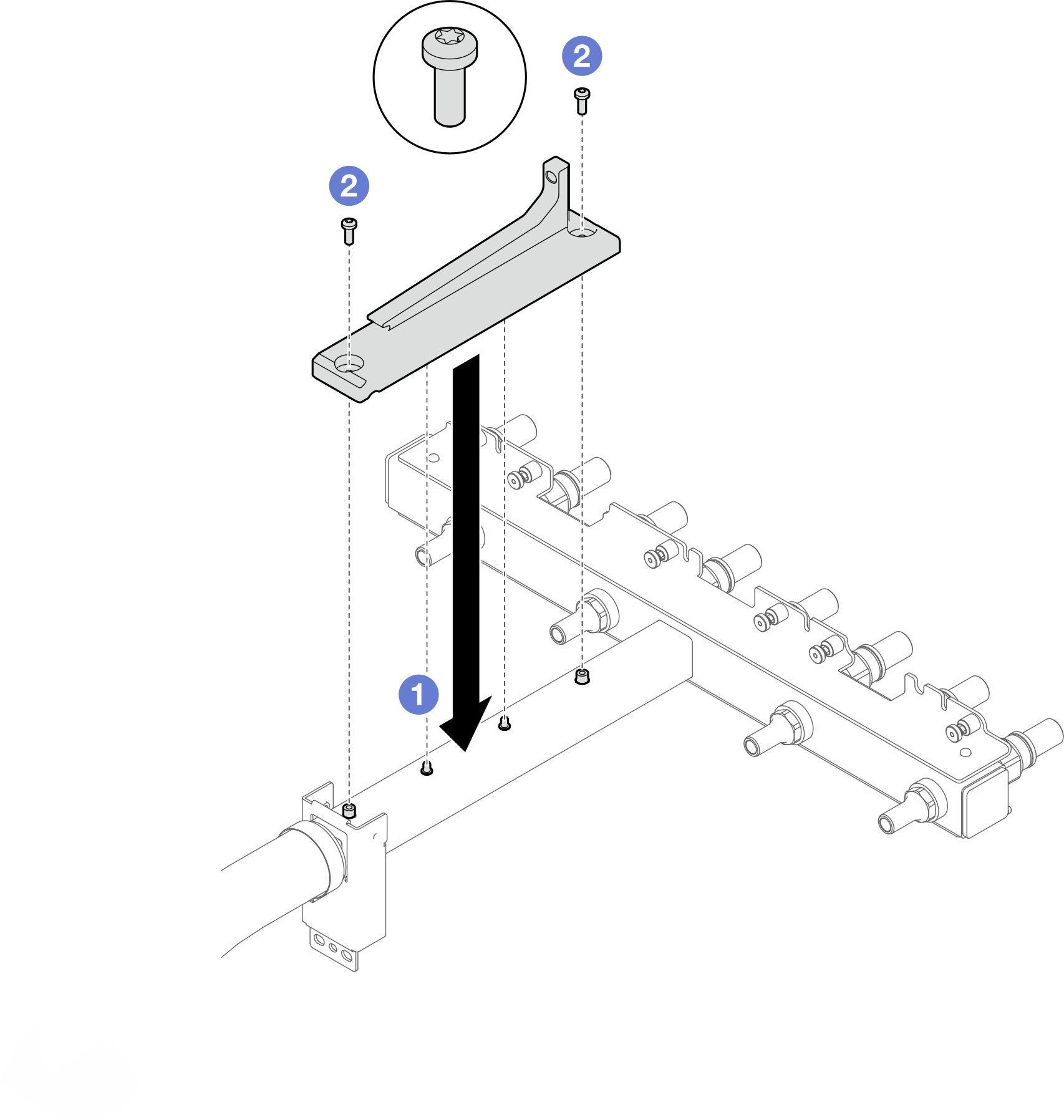
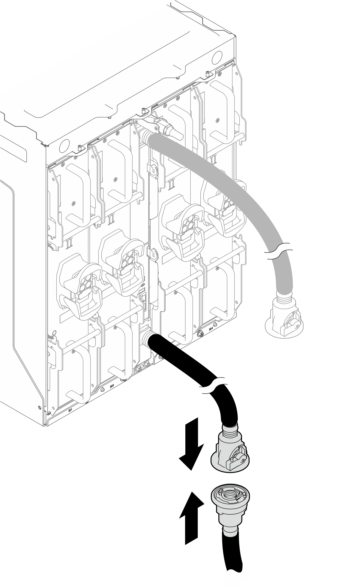
- Install the lower manifold (blue-labeled hose).
- Install the lower manifold to the enclosure.Figure 4. Installing the lower manifold.
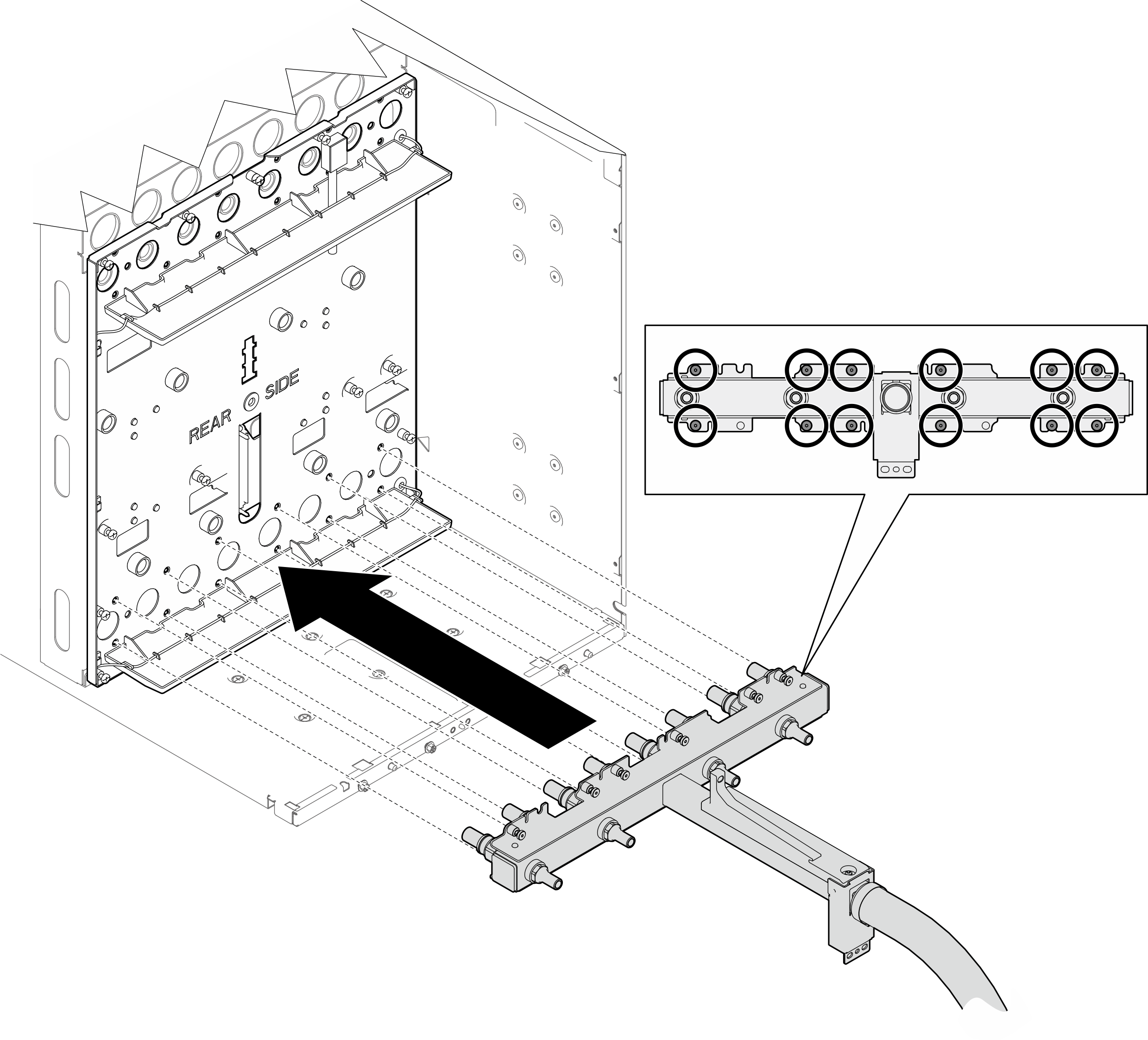
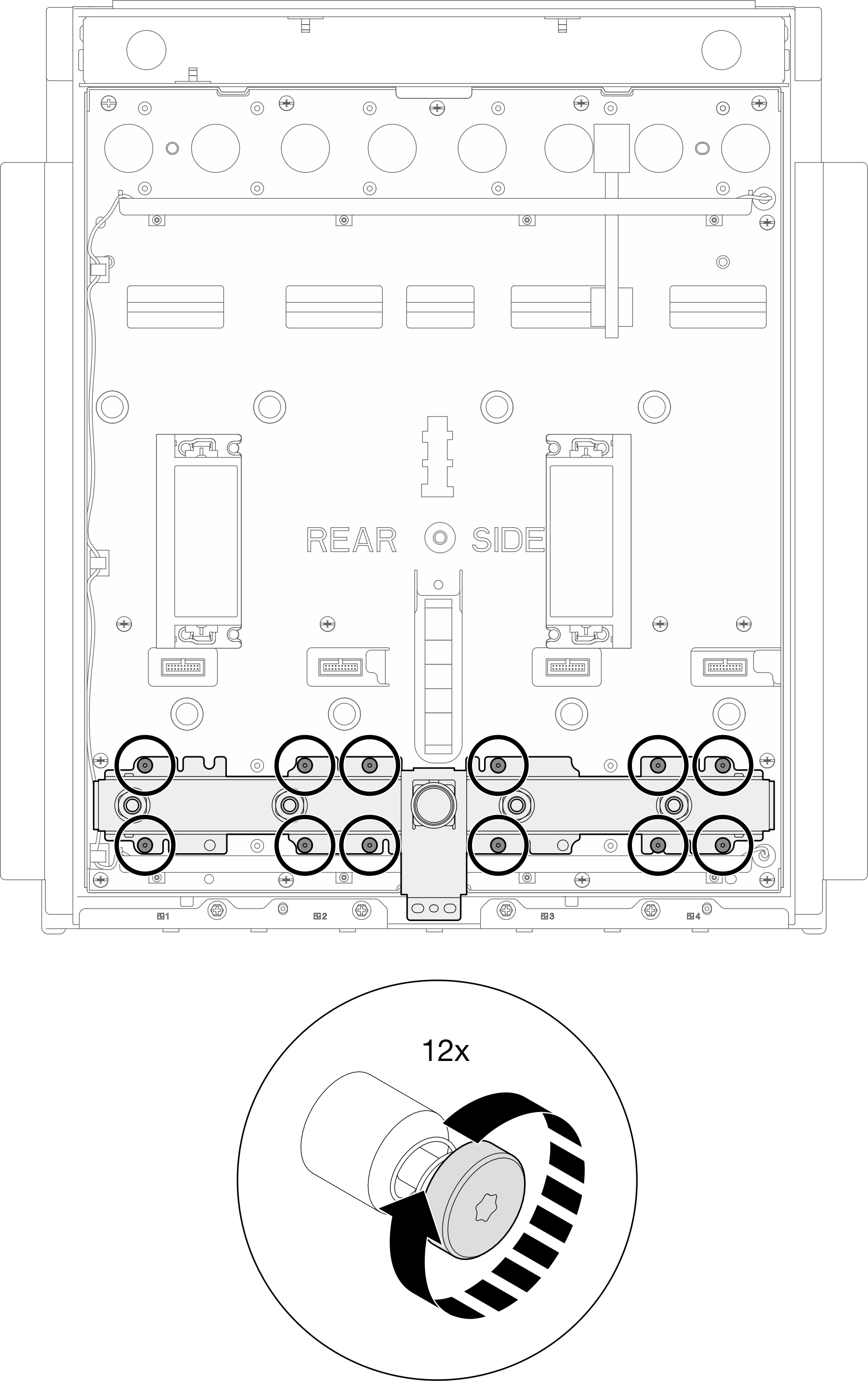
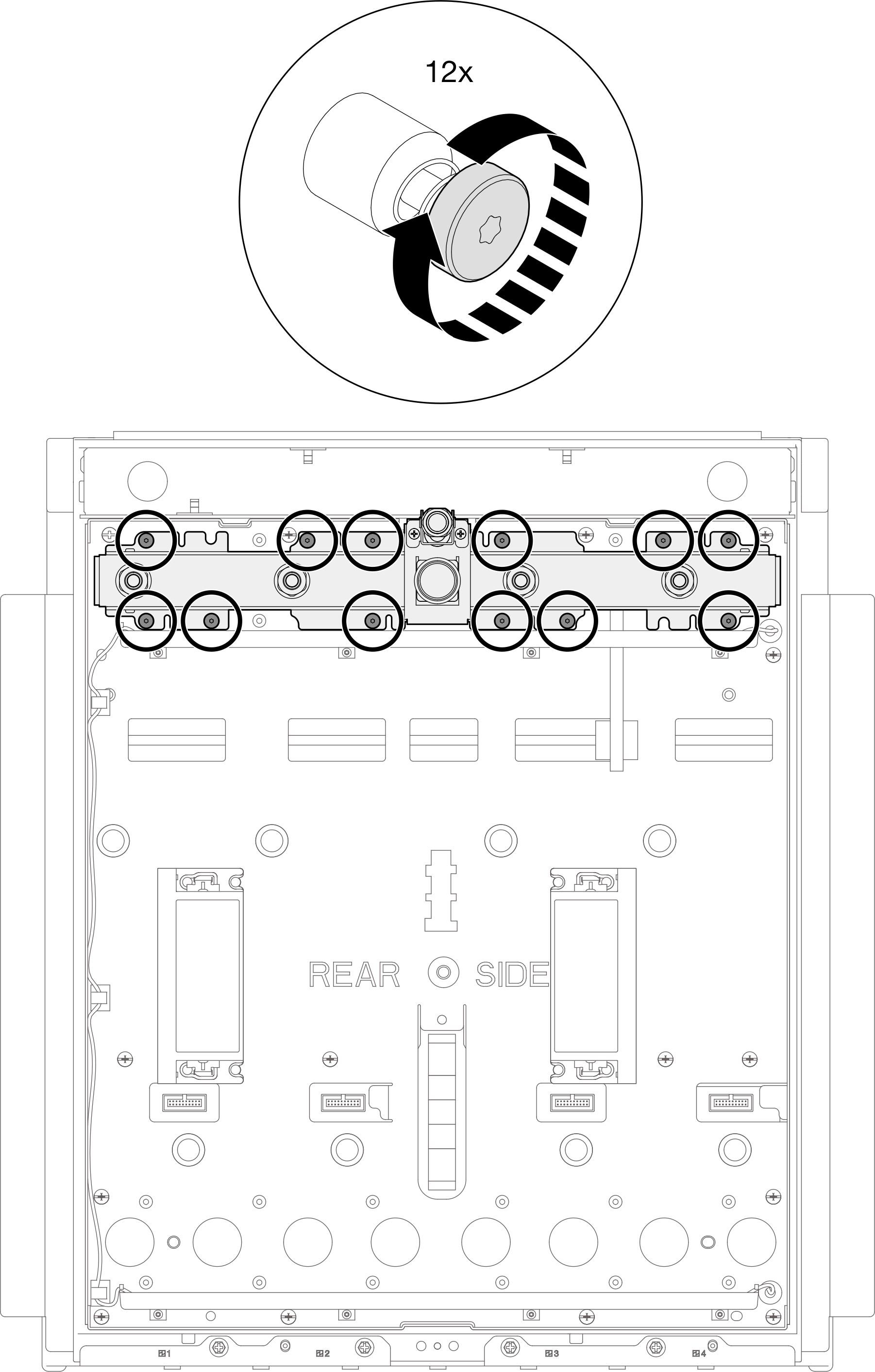
- Install twelve (x12) T10 screws to the lower manifold to secure it to the mid-plate.Figure 5. Installing screws to lower manifold
- Install two PH2 screws to secure the lower manifold to the enclosure.Figure 6. Installing screws to lower manifold

- Install the lower manifold to the enclosure.
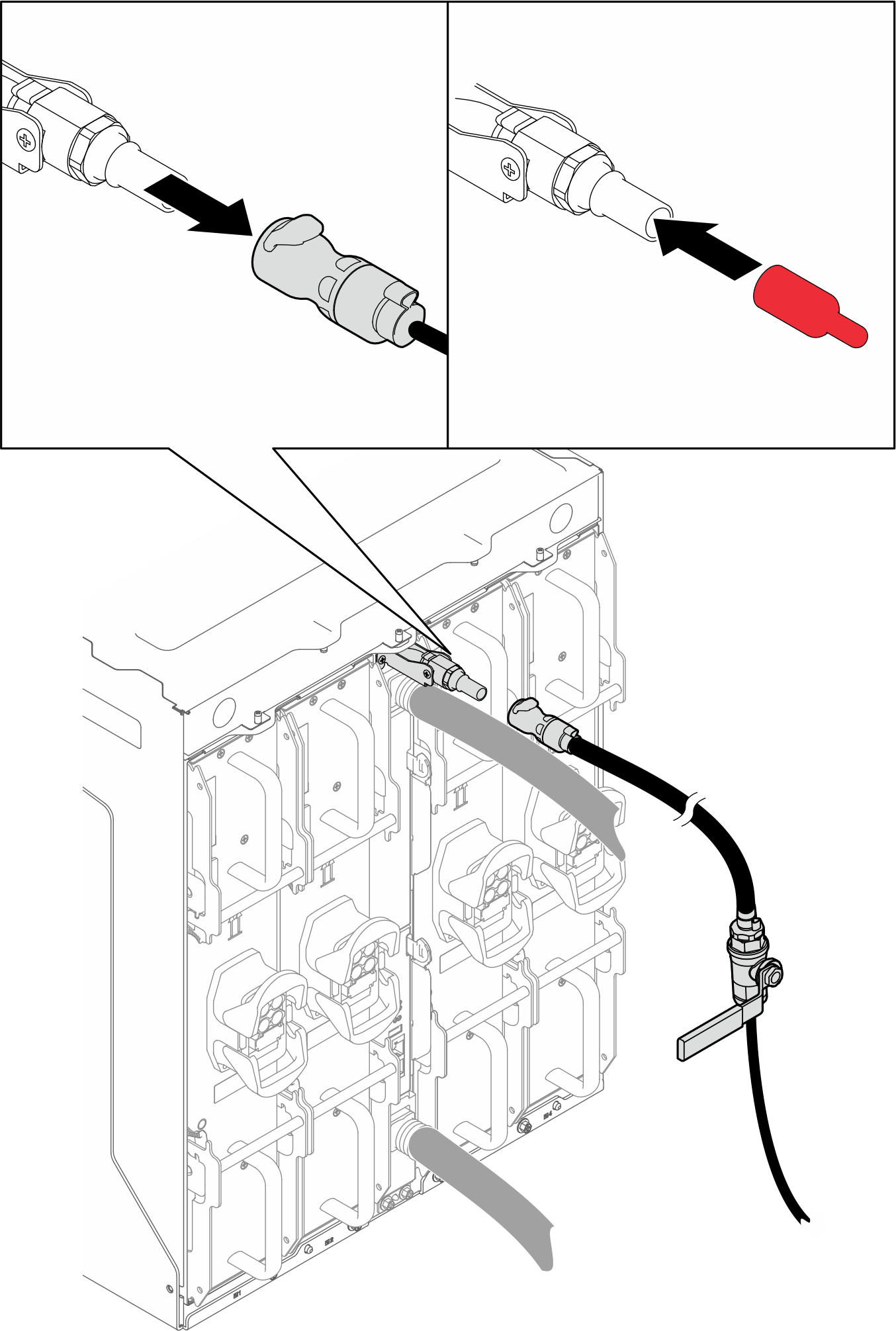
- Install the upper manifold (red-labeled hose).
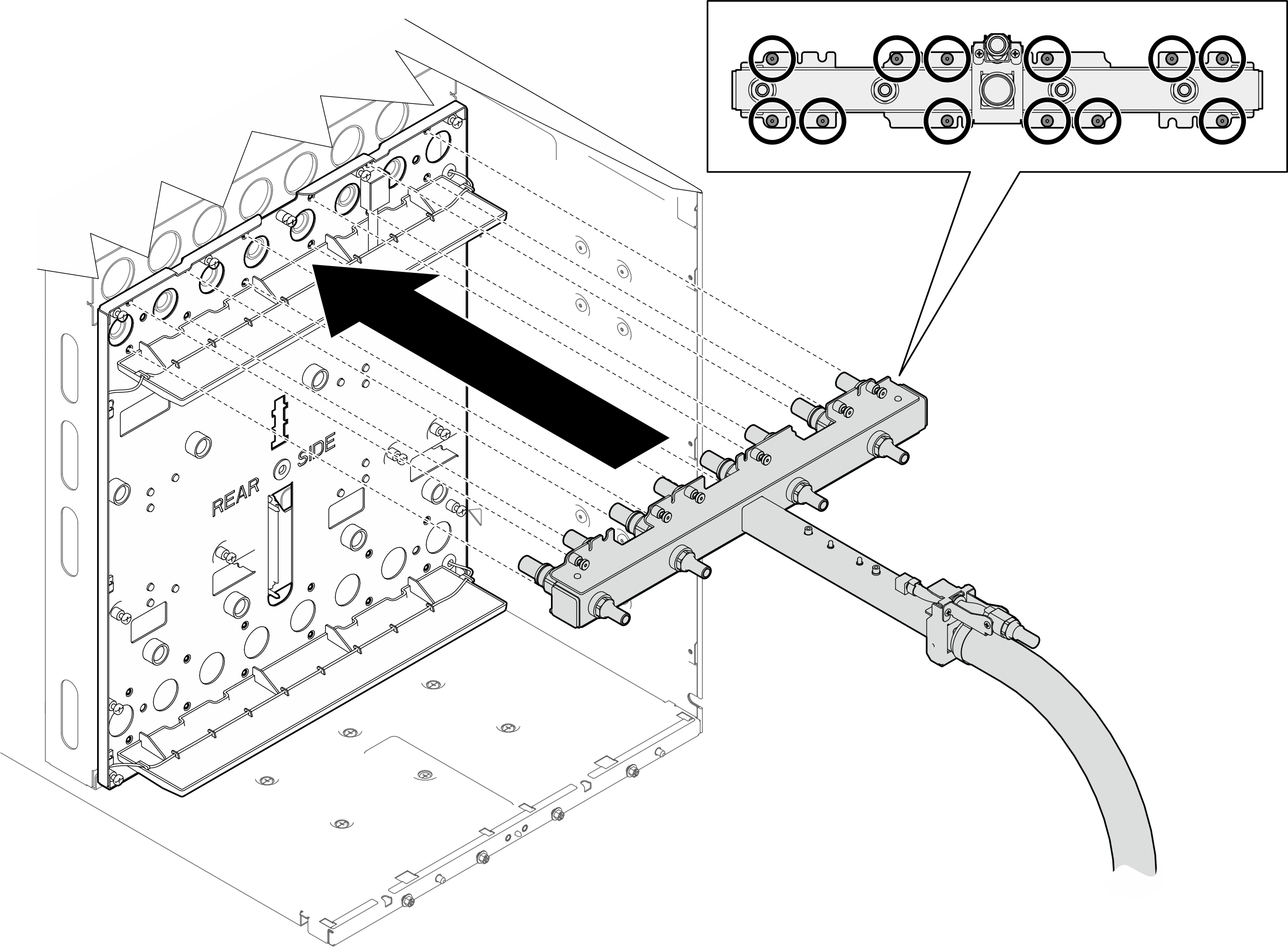
- Install the upper manifold to the enclosure with an extended screwdriver.Figure 7. Installing the upper manifold
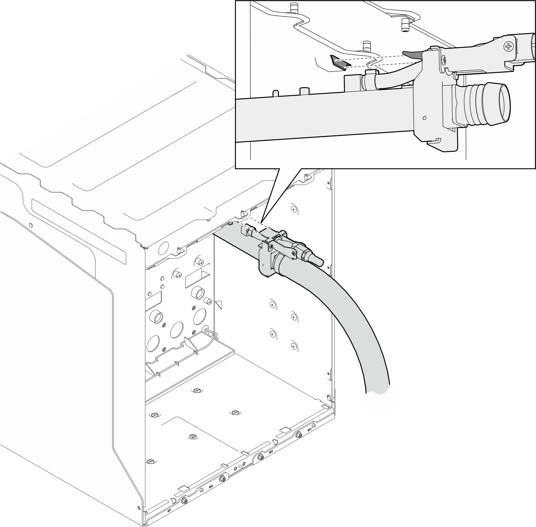
- Insert the tab on the manifold into the slot beneath the top of the enclosure.Figure 8. Inserting upper manifold tab into the slot on enclosure
- Install twelve (x12) T10 screws to the lower manifold to secure it to the mid-plate with an extended screwdriver.Figure 9. Installing screws to the upper manifold and enclosure
- Install the upper manifold to the enclosure with an extended screwdriver.
Reinstall the tray back to the enclosure
- Place the tray into the enclosure.
- Rotate the tray handles to the open position.
- Insert the tray into the tray bay in the enclosure.
Figure 10. Placing the tray into the enclosure
- Insert the tray into the tray bay while tray handles are in the open position.
- Rotate the tray handles to the open position.
- Push the tray into the enclosure until the handles bump into the enclosure edges.
Figure 11. Pushing the tray into the enclosure until handles bump into enclosure edges
- Push the tray into the enclosure until the tip of the tray handle touches the enclosure. Make sure there is no distance between the enclosure and the tip of the handle.Figure 12. Checking tray handle position
 Figure 13. Distinguishing correct tray handle position
- Rotate the bottom handle for 45 degrees to push the tray slightly into the enclosure. DO NOT rotate the bottom handle all the way in.NoteIf the tray does
not move into the enclosure as you rotate the bottom handle, the handles are not in correct position. Reinstall the tray until the handles are seated correctly and handle rotation can bring about tray movement. Figure 14. Slightly rotating bottom tray handle to move the tray forward
- Rotate both top and bottom handles to the closed position to secure the tray in the enclosure.Figure 15. Rotating both tray handles to the closed position

- Make sure the tray does not protrude from the enclosure. The surface of the tray front bezel and the enclosure outer frame should be aligned as a flat surface.Figure 16. Tray front bezel and enclosure outer frame surface alignment

Perform manifolds bleeding
- Close the valve of the upper bleeder.Figure 17. Closing the valve of the upper bleeder

- Remove the cover from bleeder port on the upper manifold. Then, connect the upper bleeder to the bleeder port.Figure 18. Connecting upper bleeder to the bleeder port on the upper manifold

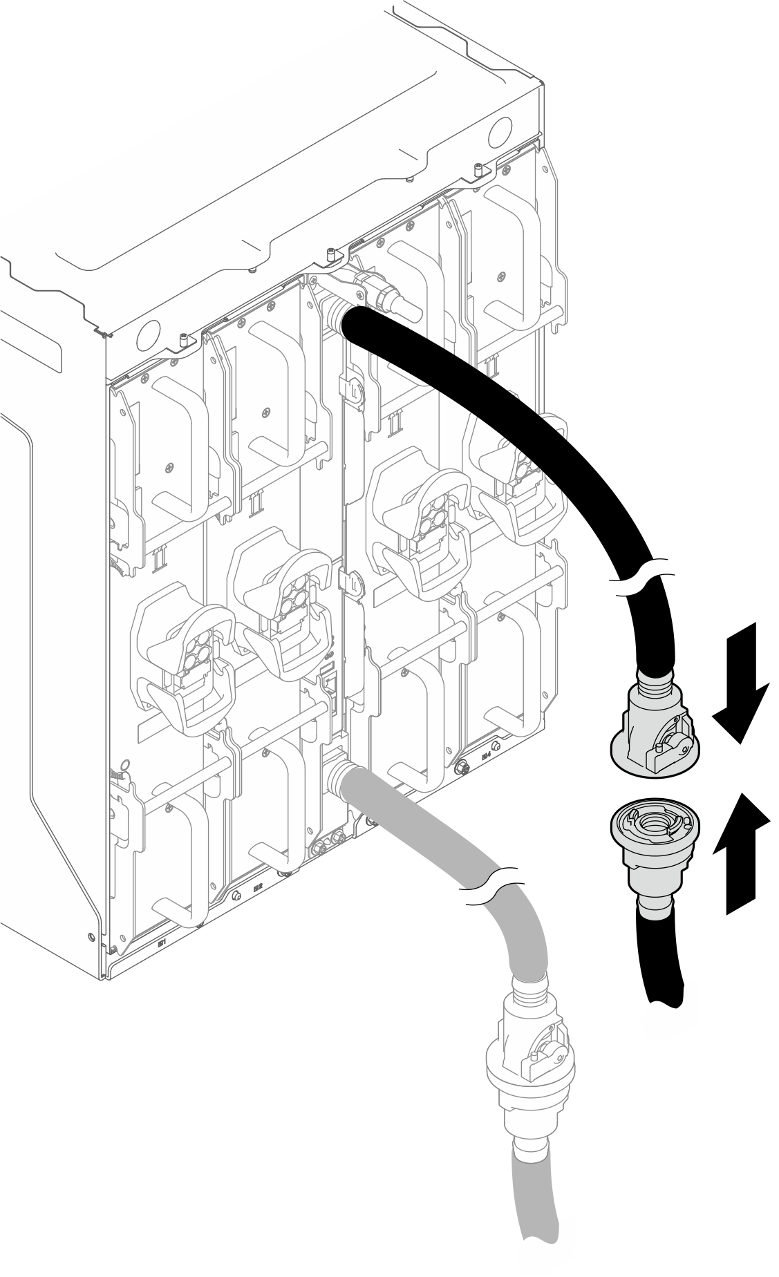
- Connect the facility supply hose to the lower manifold.Figure 19. Connecting facility supply hose to the lower manifold
- Partially open the valves of the lower manifold and the facility supply hose.
- Press the button on the ball valve switch
- Partially rotate the switch to open the valve, about 1/4 of the way.
NoteDo not fully open the ball valves or you will reduce your ability to control the flow as you fill the rack.Figure 20. Partially open the valves of the lower manifold and the facility supply hose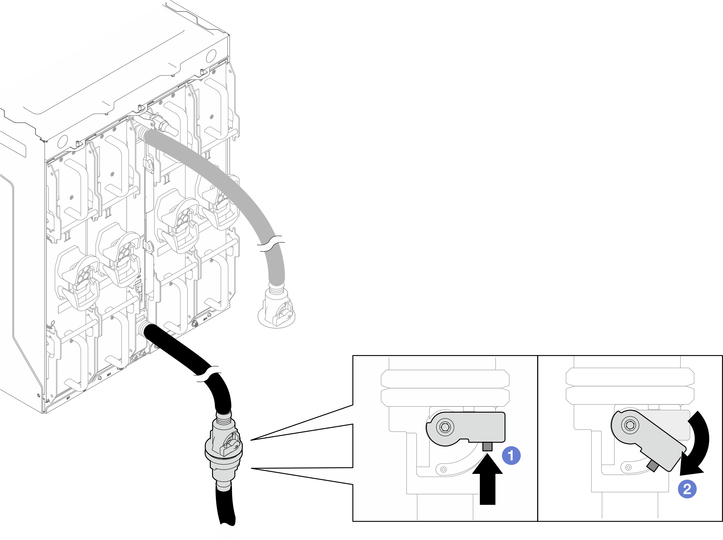
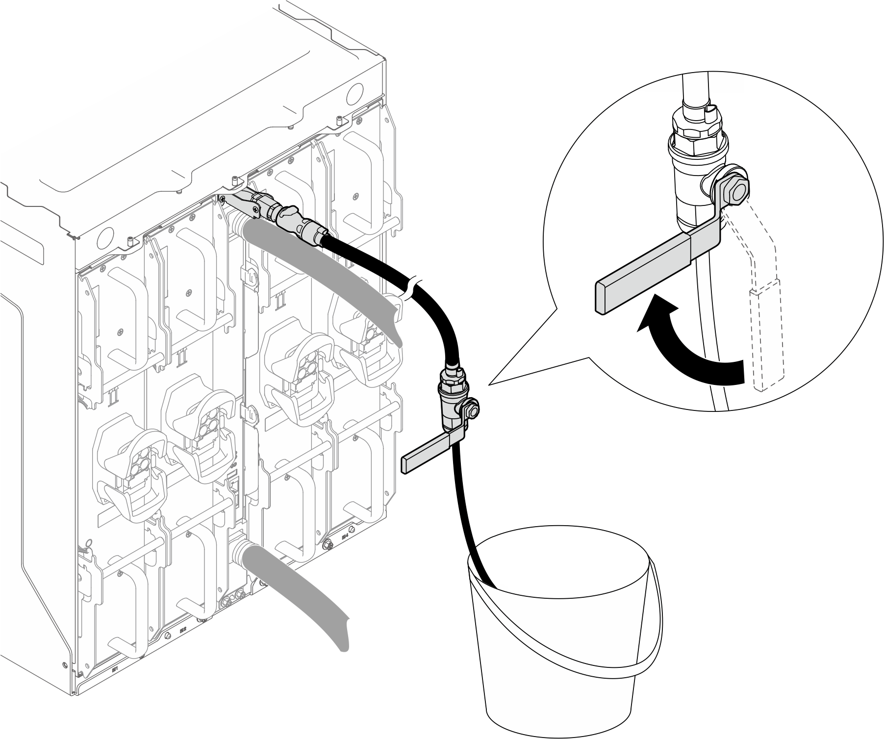
- Slowly open the valve of the upper bleeder to allow a steady stream of water to drain.Figure 21. Opening the valve of the upper bleeder

- Close the valve of the upper bleeder after a steady stream of water flows into the bucket or there are only minimal bubbles in the bleeder hose.Figure 22. Closing the valve of the upper bleeder
- Disconnect the upper bleeder from the upper manifold. Reinstall the cover to the bleeder port.Figure 23. Disconnecting upper bleeder from manifold
- Connect the facility return hose to the upper manifold.Figure 24. Connecting return hose to the upper manifold
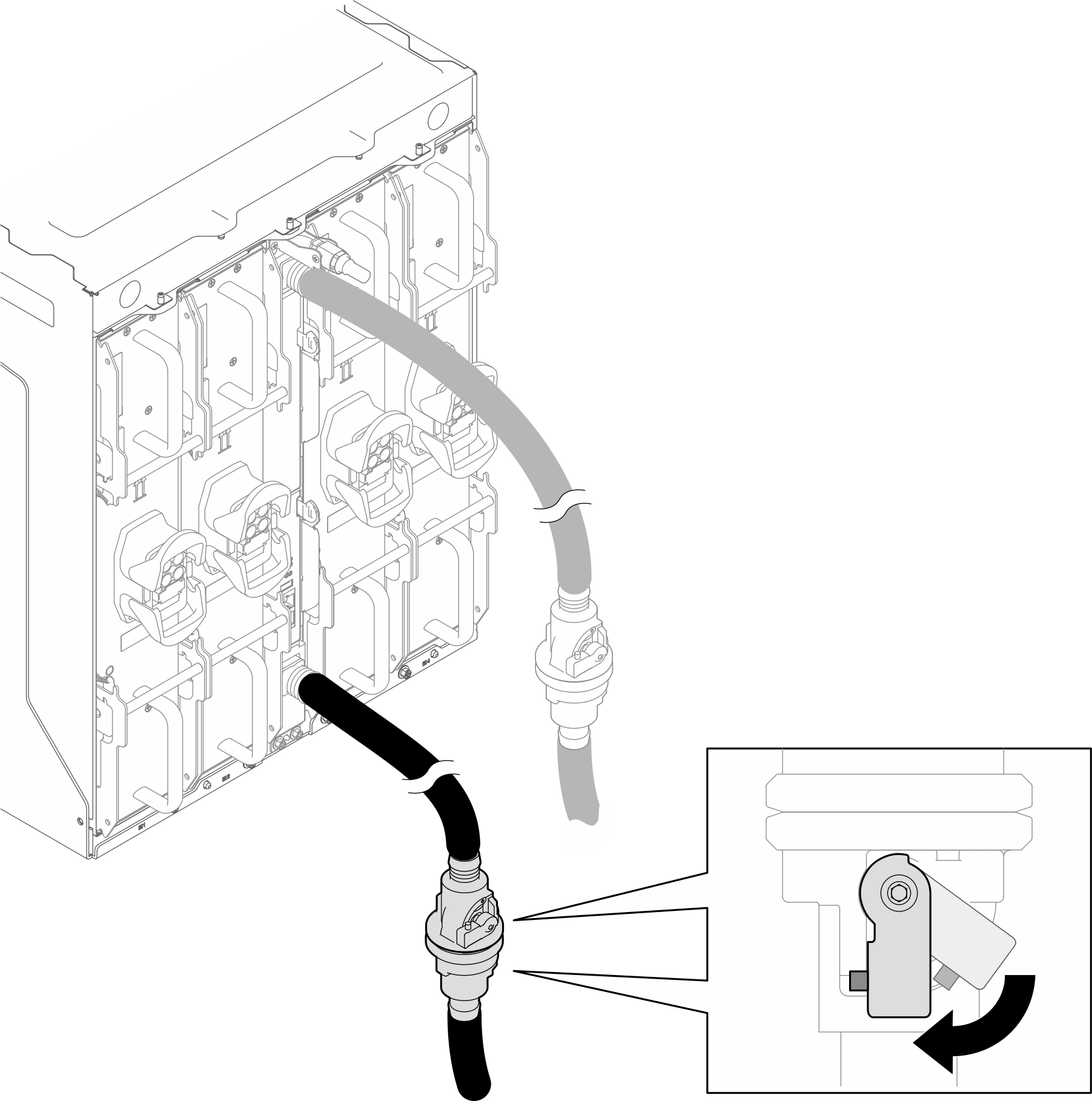
- Open the valves of the upper manifold and the facility return hose.
- Press the button on the ball valve switch
- Rotate the switch to open the valves as illustrated below.
Figure 25. Opening the valves of the upper manifold and the facility return hose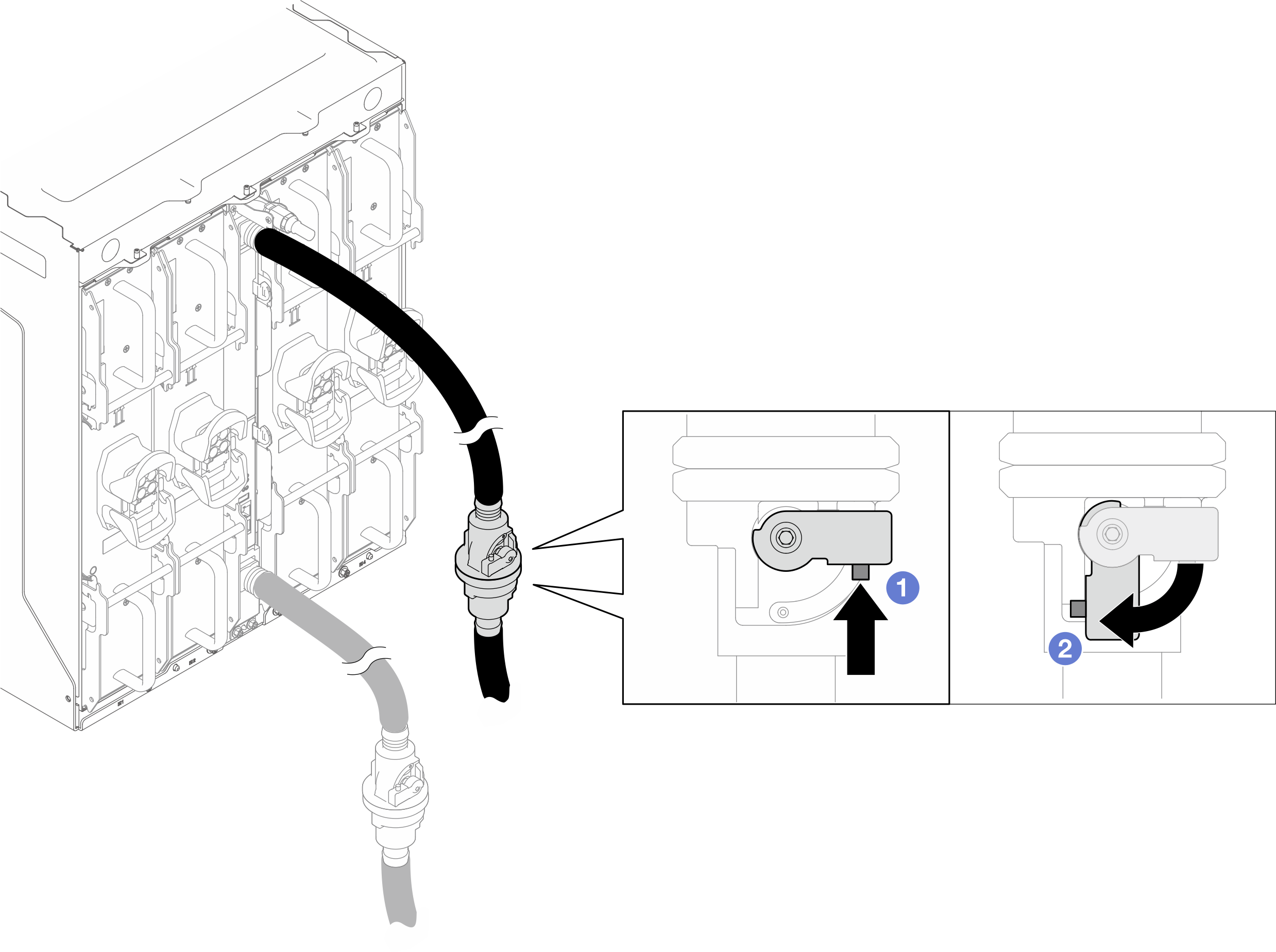
- Fully open the valves of the lower manifold and the facility supply hose.Figure 26. Fully opening the valves of the lower manifold and the facility supply hose.
- Install the power cord.AttentionDo not connect power cords to the PCS when performing manifold draining and bleeding process.
- Rotate the power socket latches to the open position.
- Connect the power cord into the power socket.
 Rotate the latches to the closed position to secure the power cord in place.
Figure 27. Connecting the PCS power cord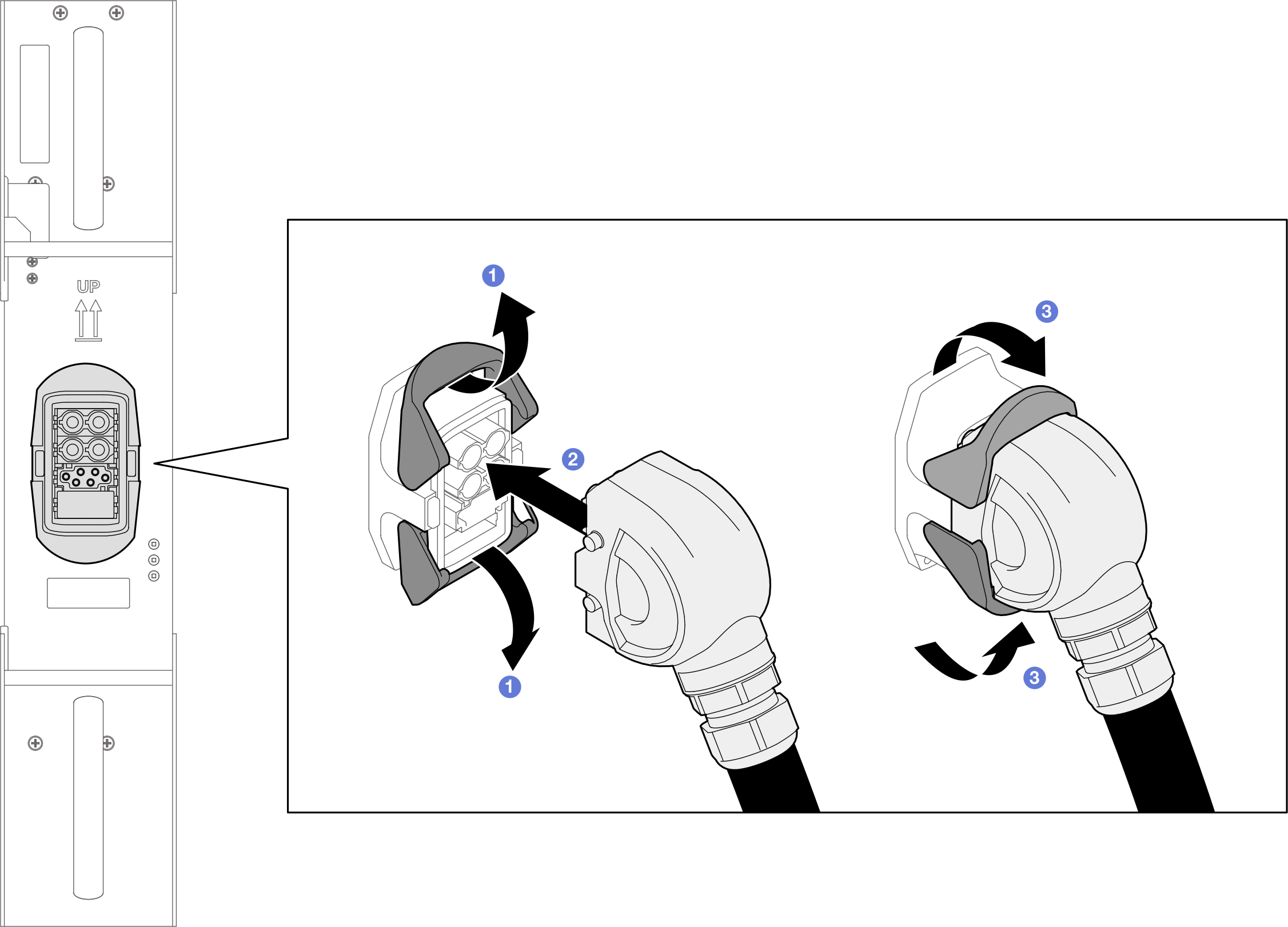
Install the SMM3. See Install the SMM3.
Install the blank filler. See Install the blank filler.
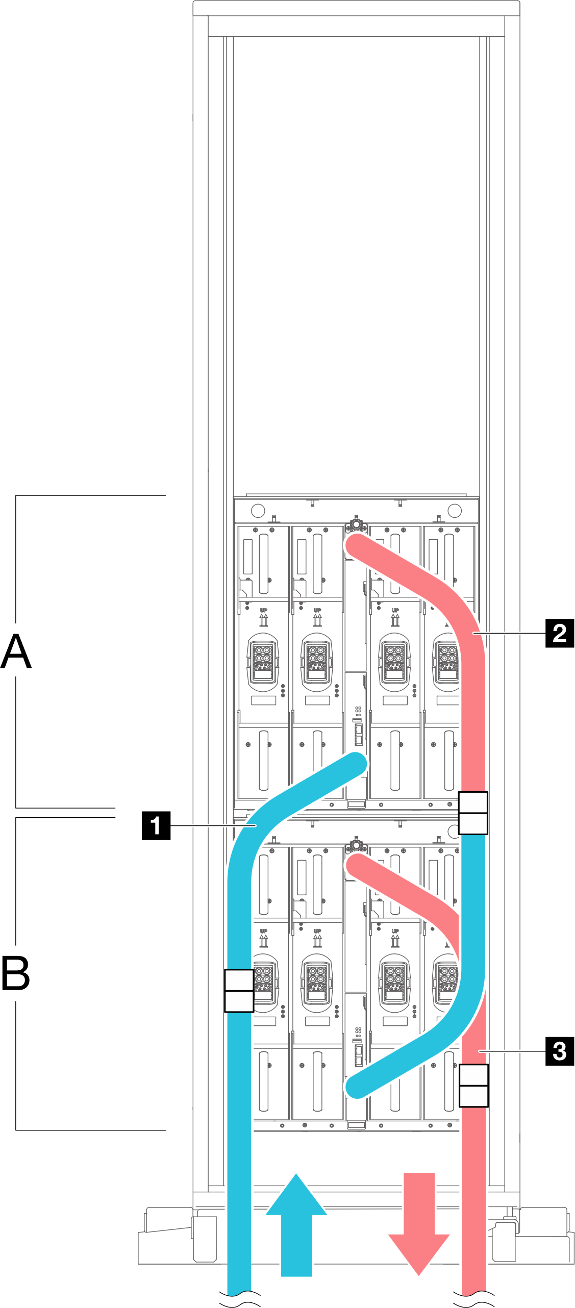
Use the Velcro ties on the rack frame to secure the manifold hoses. See the illustrations below for the locations of the Velcro ties.
Figure 28. Velcro ties for securing manifold hoses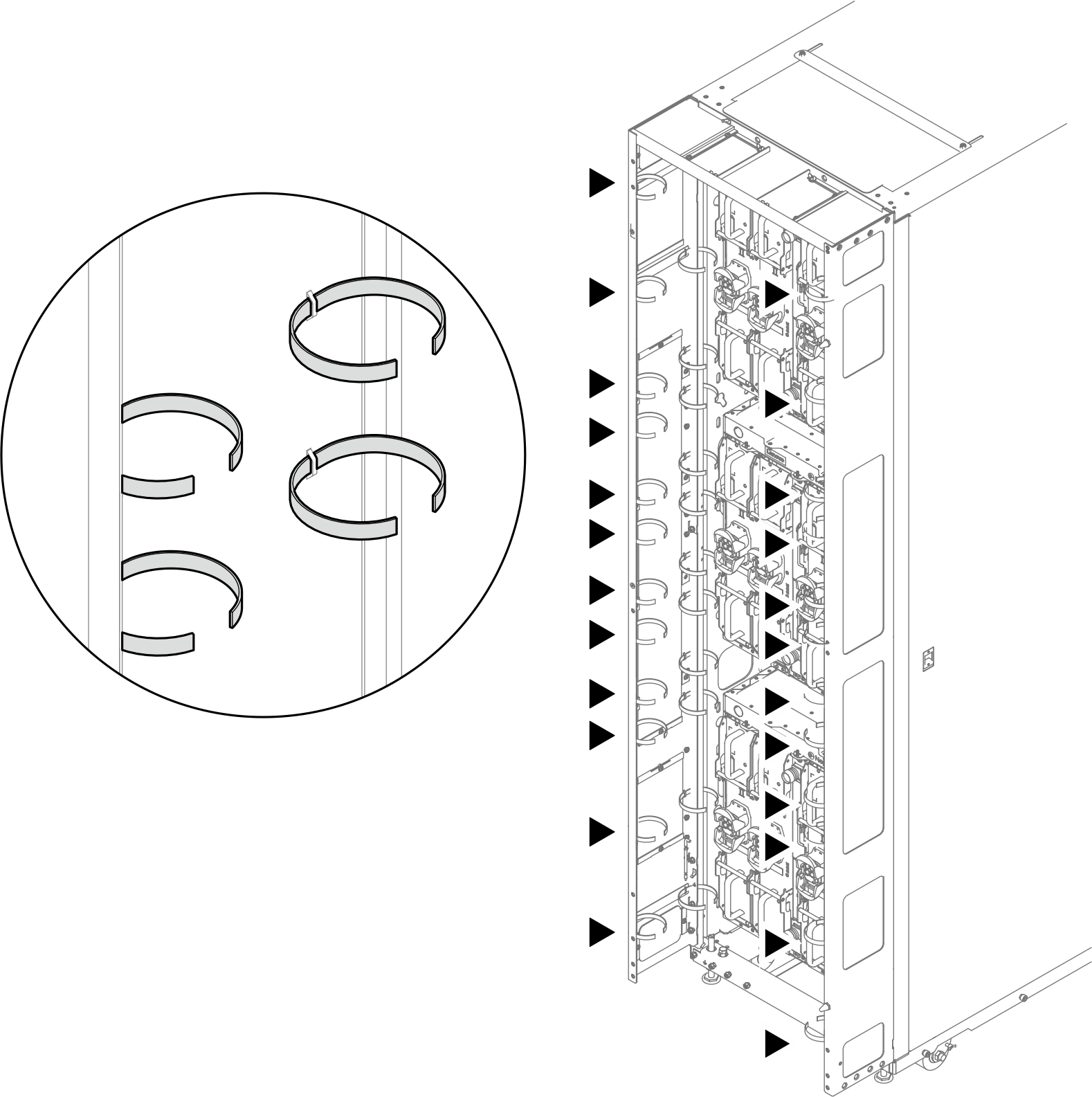
| A First enclosure |
| B Second enclosure |
| 1 Hose supply of first enclosure—connecting to facility supply |
| 2 Hose return of first enclosure—connecting to hose supply of second enclosure |
| 3 Hose return of second enclosure—connecting to facility return |
| Blue indicates supply, and red indicates return. |