Install a memory module
Follow instructions in this section to install a memory module.
About this task
See Memory module installation rules and order for detailed information about memory configuration and setup.Read Installation Guidelines and Safety inspection checklist to ensure that you work safely.
Make sure to remove or install memory module 20 seconds after disconnecting power cords from the system. It allows the system to be completely discharged of electricity and safe for handling memory module.
Make sure to adopt one of the supported configurations listed in Memory module installation rules and order.
- Memory modules are sensitive to static discharge and require special handling. Refer to the standard guidelines at Handling static-sensitive devices:
Always wear an electrostatic-discharge strap when removing or installing memory modules. Electrostatic-discharge gloves can also be used.
Never hold two or more memory modules together so that they do not touch each other. Do not stack memory modules directly on top of each other during storage.
Never touch the gold memory module connector contacts or allow these contacts to touch the outside of the memory module connector housing.
Handle memory modules with care: never bend, twist, or drop a memory module.
Do not use any metal tools (such as jigs or clamps) to handle the memory modules, because the rigid metals may damage the memory modules.
Do not insert memory modules while holding packages or passive components, which can cause package cracks or detachment of passive components by the high insertion force.
Go to Drivers and Software download website for ThinkEdge SE100 to see the latest firmware and driver updates for your server.
Go to Update the firmware for more information on firmware updating tools.
Procedure
- Make preparation for this task.
- Locate the memory module slot on the system board.Figure 1. Memory modules and processor layout
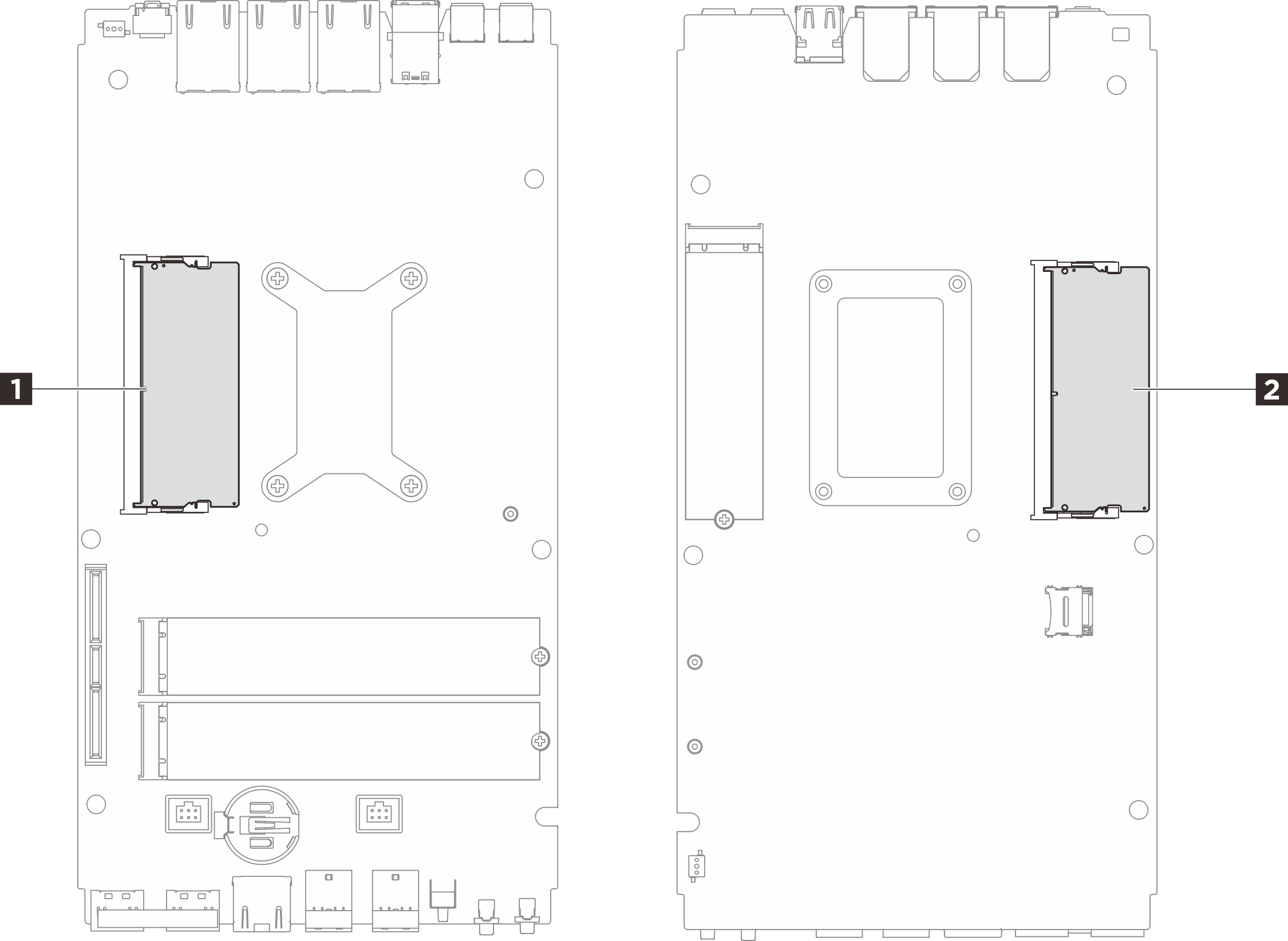
Table 1. Location of memory modules 1 DIMM slot 1 (top side) 2 DIMM slot 2 (bottom side) - Replace the thermal pad and ESD absorbent pad if the pads are in any of the following conditions.
- The thermal pad is damaged or detached from the surface.
- The new part to be installed is of different brand or form factor from the replaced one; the new part might cause thermal pads to be deformed or damaged.
Figure 2. Memory module slot 1 thermal pads (Top cover & system board side)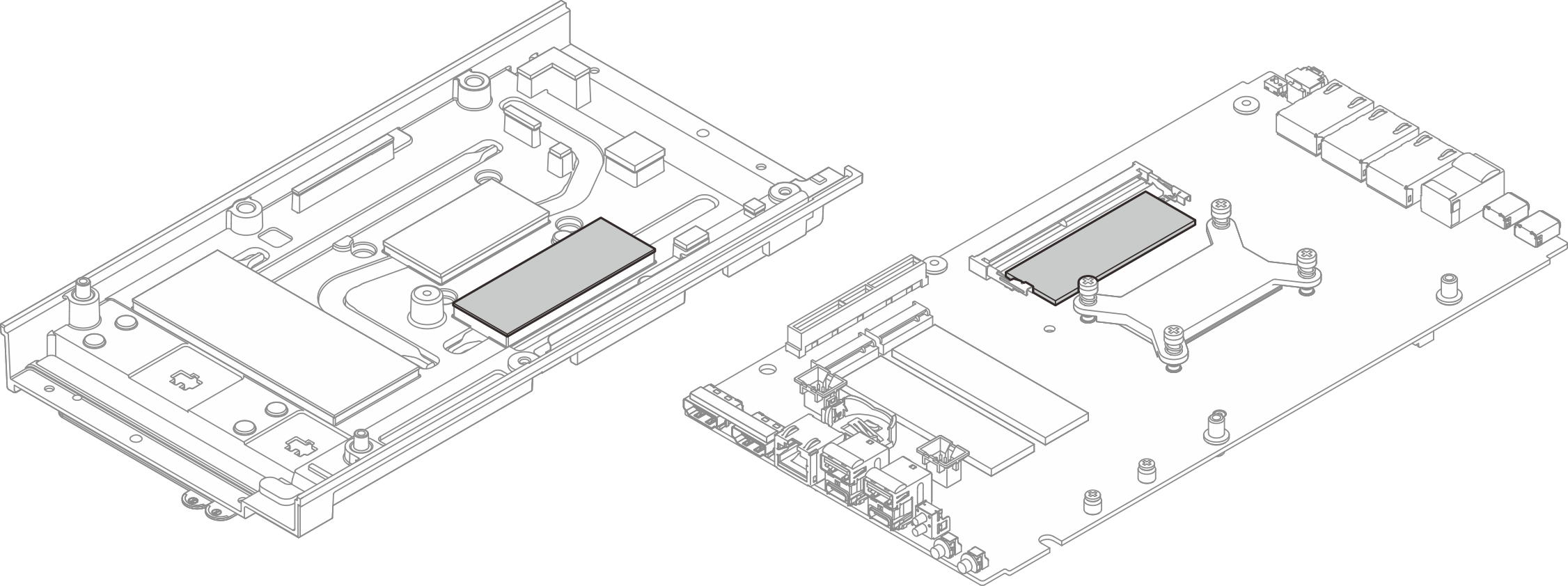 Figure 3. Memory module slot 2 thermal pads (Bottom cover & system board side)
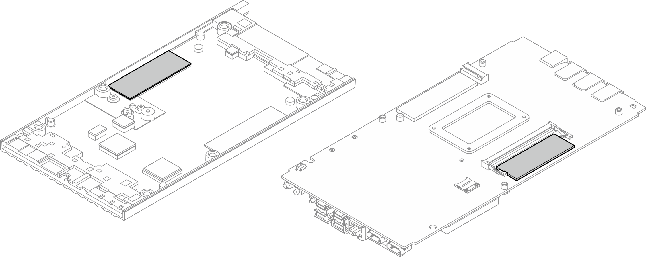
- Locate the memory module slot on the system board.
- Touch the static-protective package that contains the memory module to any unpainted surface on the outside of the server. Then, take the memory module out of the package and place it on a static-protective surface.
- Install the memory module into the slot.
 Align the notch on the memory module with the tab on the memory module slot; then insert the memory module at an angle of approximately 30 degrees into the slot.
 Press the memory module down until it clicks into place.NoteMake sure the securing pins are fully locked and the gold finger is fully inserted into the slot as illustrated.Figure 4. Memory module installation
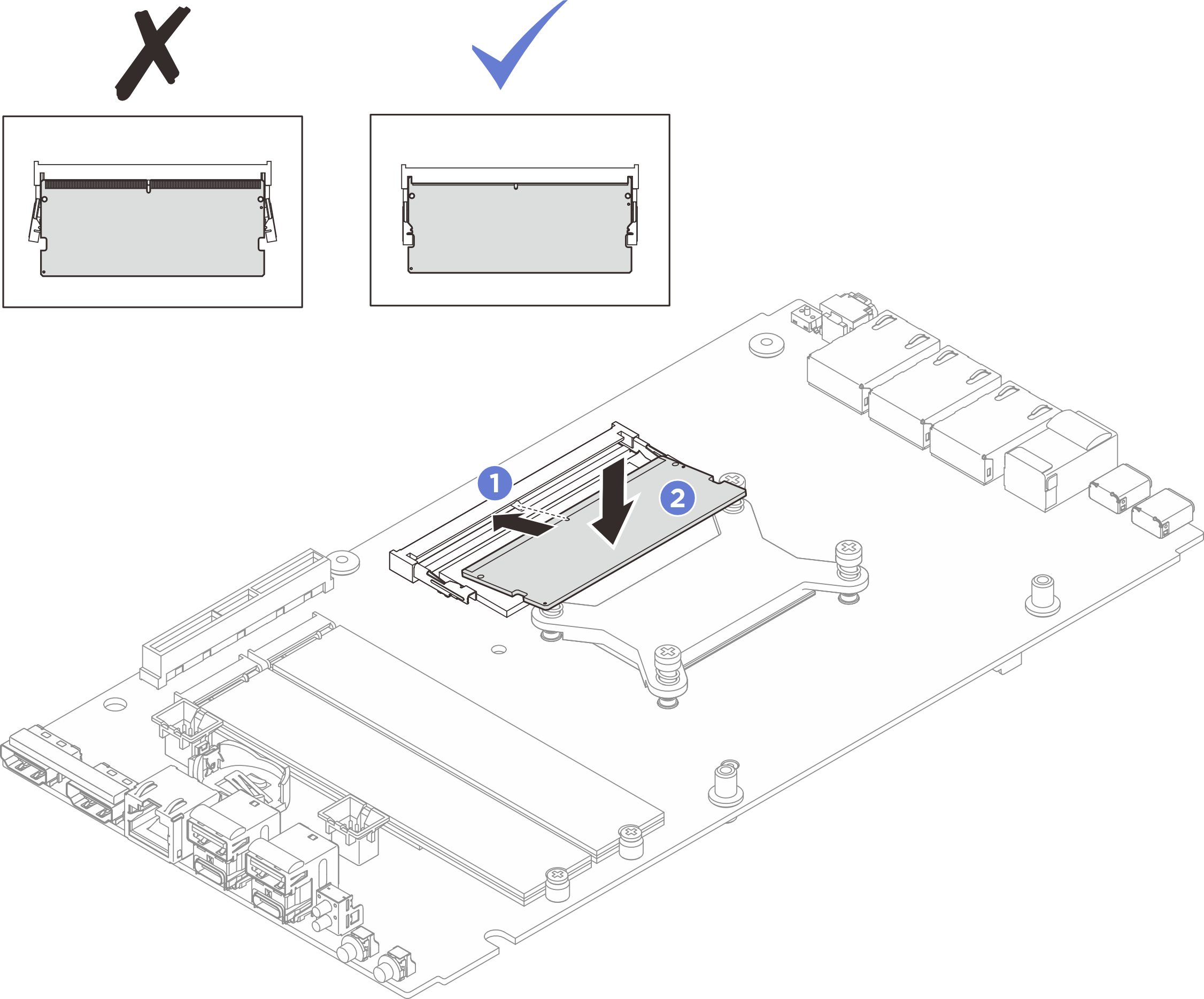
After you finish
- If applicable, install the top cover. See Install the top cover.
- If applicable, install the bottom cover. See Install the bottom cover.
- Install the expansion kit or the expansion filler. See Install the expansion kit or Install the expansion filler.
- Install the fan shroud. See Install the fan shroud.
- Complete the parts replacement. See Complete the parts replacement.
Demo video