Install the bottom cover
Follow instructions in this section to install the bottom cover.
About this task


Hazardous energy present. Voltages with hazardous energy might cause heating when shorted with metal, which might result in spattered metal, burns, or both.
Read Installation Guidelines and Safety inspection checklist to ensure that you work safely.
Ensure that all components have been reassembled correctly and that no tools or loose screws are left inside your server.
Required tools
Make sure you have the required tools listed below in hand to properly replace the component.- Prepare the following screwdrivers:
- Phillips #1 head screwdriver
- Phillips #2 head screwdriver
Procedure
- Make preparation for this task.
- Check the thermal pads on the bottom cover. If a thermal pad is damaged or detached from the cover, replace it with a new one. See Thermal pad installation guidelines to identify the required thermal pad kit and follow the thermal pad instructions.Figure 1. Bottom cover thermal pads
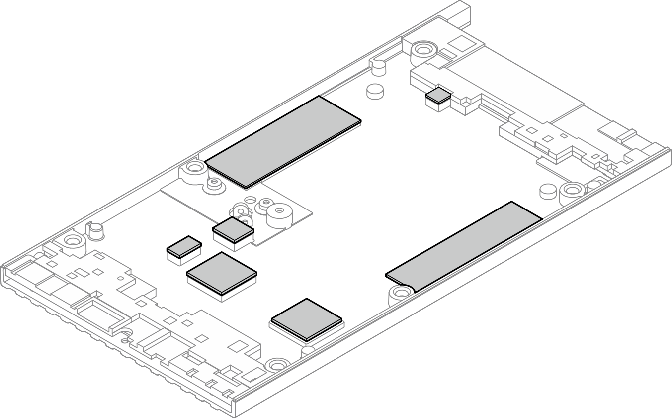
- Check the thermal pads on the bottom cover. If a thermal pad is damaged or detached from the cover, replace it with a new one. See Thermal pad installation guidelines to identify the required thermal pad kit and follow the thermal pad instructions.
- Install the bottom cover.
 Align the bottom cover with the guiding slots on both sides of the node; then, lower the bottom cover onto the node.
 Insert the front and rear I/O brackets into the node until they are seated in place.Figure 2. Installing the bottom cover
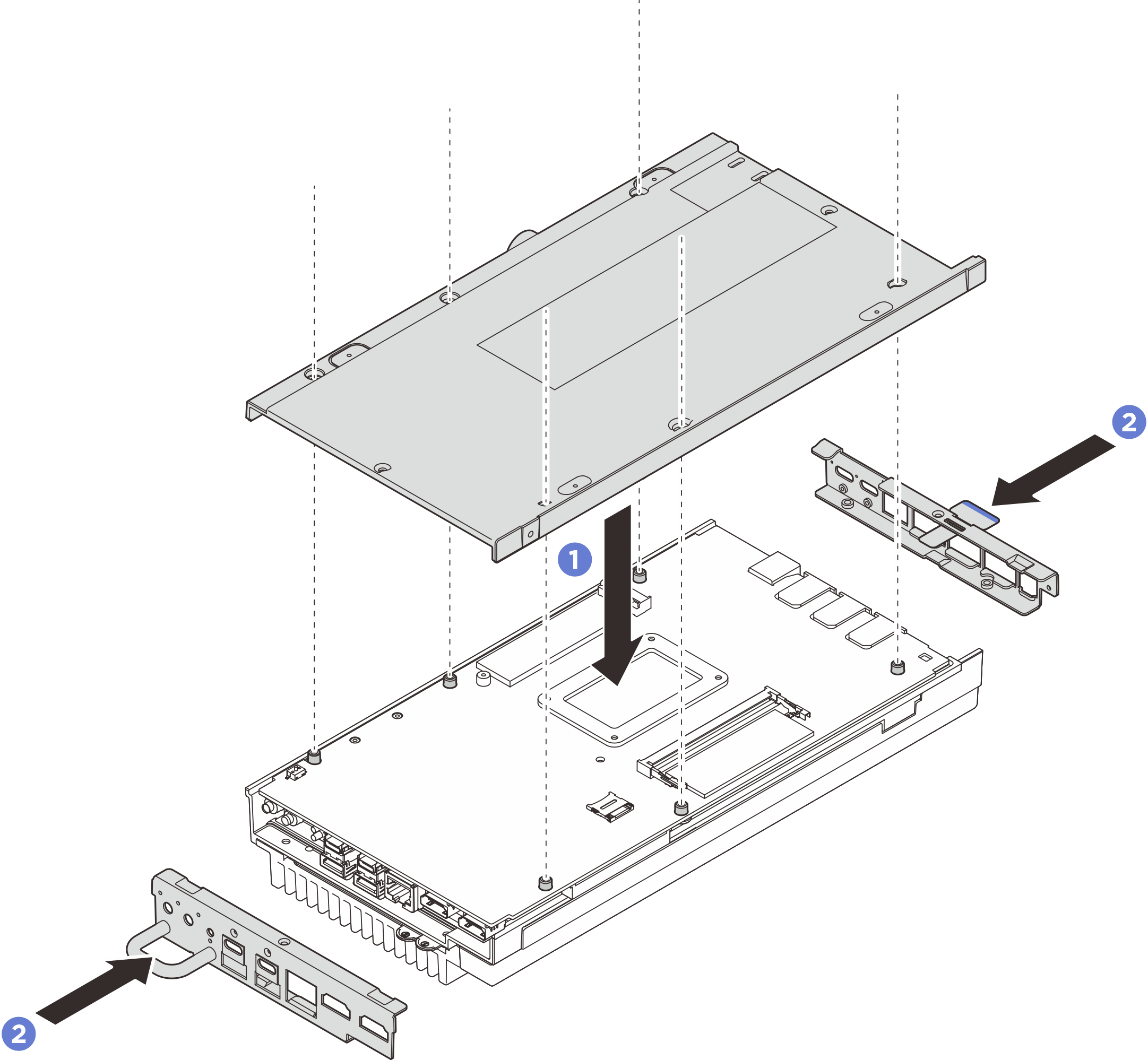
- Tighten screws to secure the cover.
- Tighten two Phillips #1 screws to the short sides of the bottom cover.
The Phillips #1 screws are with pre-appliced white threadlocking adhesive, and the corresponding screw holes are circled by white color. Make sure to fasten the screws to the corresponding holes.
- Tighten six Phillips #2 screws to the long sides of the bottom cover as illustrated; then reverse the node and place the top side facing up.
 Slide the pull-out information tabs outward from the node.
 Tighten four Phillips #1 screws to the short sides of the top cover.Note
The Phillips #1 screws are with pre-appliced white threadlocking adhesive, and the corresponding screw holes are circled by white color. Make sure to fasten the screws to the corresponding holes.
Make sure to slide the pull-out information tabs back once the screw underneath is fully installed.
Figure 3. Installing the screws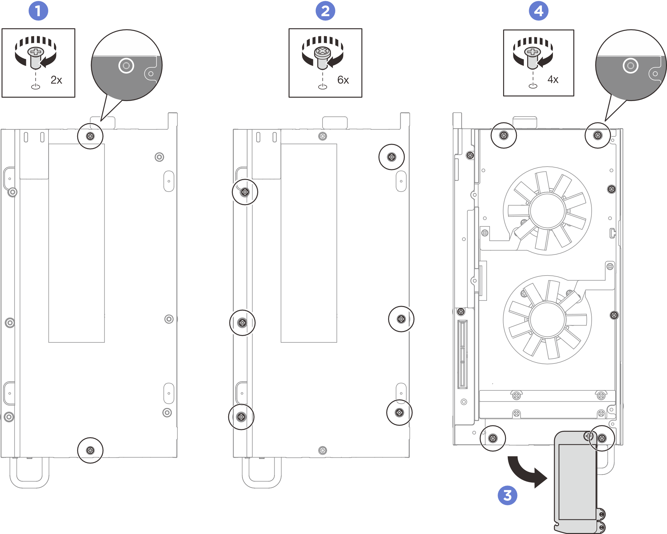
- Install the fan shroud. See Install the fan shroud.
- Install the expansion kit or the expansion filler. See Install the expansion kit or Install the expansion filler.
- Complete the parts replacement. See Complete the parts replacement.
Demo video