Remove the top cover
Follow instructions in this section to remove the top cover.
About this task
Hazardous energy present. Voltages with hazardous energy might cause heating when shorted with metal, which might result in spattered metal, burns, or both.
Read Installation Guidelines and Safety inspection checklist to ensure that you work safely.
Power off the server and peripheral devices and disconnect the power cords and all external cables. See Power off the server.
If the node is installed in an enclosure or mounted, remove the node from the enclosure or mount. See Configuration guide.
Required tools
Make sure you have the required tools listed below in hand to properly replace the component.- Prepare the following screwdrivers:
- Phillips #1 head screwdriver
- Phillips #2 head screwdriver
Procedure
- Remove the screws from the top cover.
 Slide the pull-out information tabs outward from the node.
 Remove the four Phillips #1 screws located on the short side of the top cover.Note
Make sure to slide the pull-out information tabs back once the screw underneath is fully removed.
 Remove the four Phillips #2 screws located on the long side of the top cover; then, reverse the node and place the bottom side of the node facing up.Note
The screws to be removed might be covered by fan cables. Carefully pull the fan cable out a little bit to remove the screw underneath, and put the cable back after removing the screw.
Figure 1. Removing screws from the top cover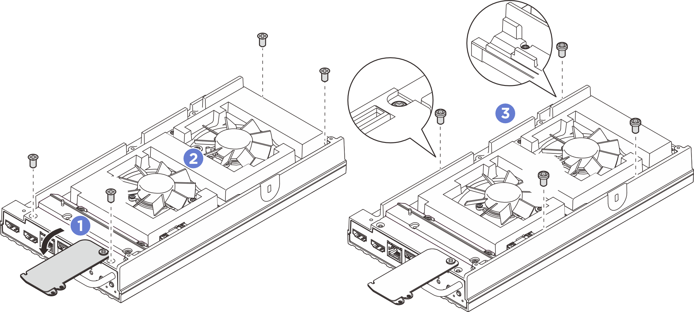
- Remove the front and rear I/O brackets.
- Loosen the two Phillips #1 screws located on the short side of the bottom cover.
- Loosen the two Phillips #2 screws located on the long side of the bottom cover.
- Hold the blue touch points on the rear side of the node and the I/O bracket handle on the front side of the node; then pull the front and rear I/O brackets from the node.
Figure 2. Removing the front and rear I/O brackets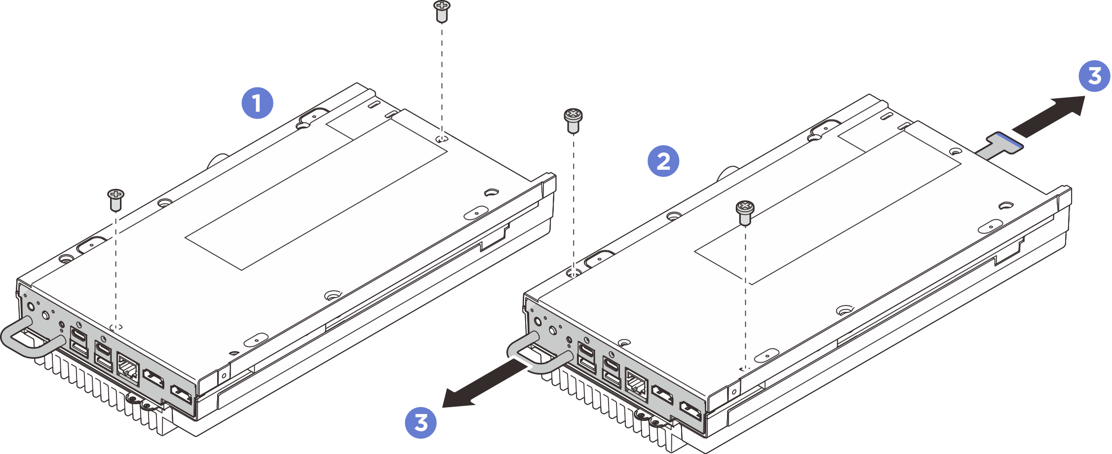
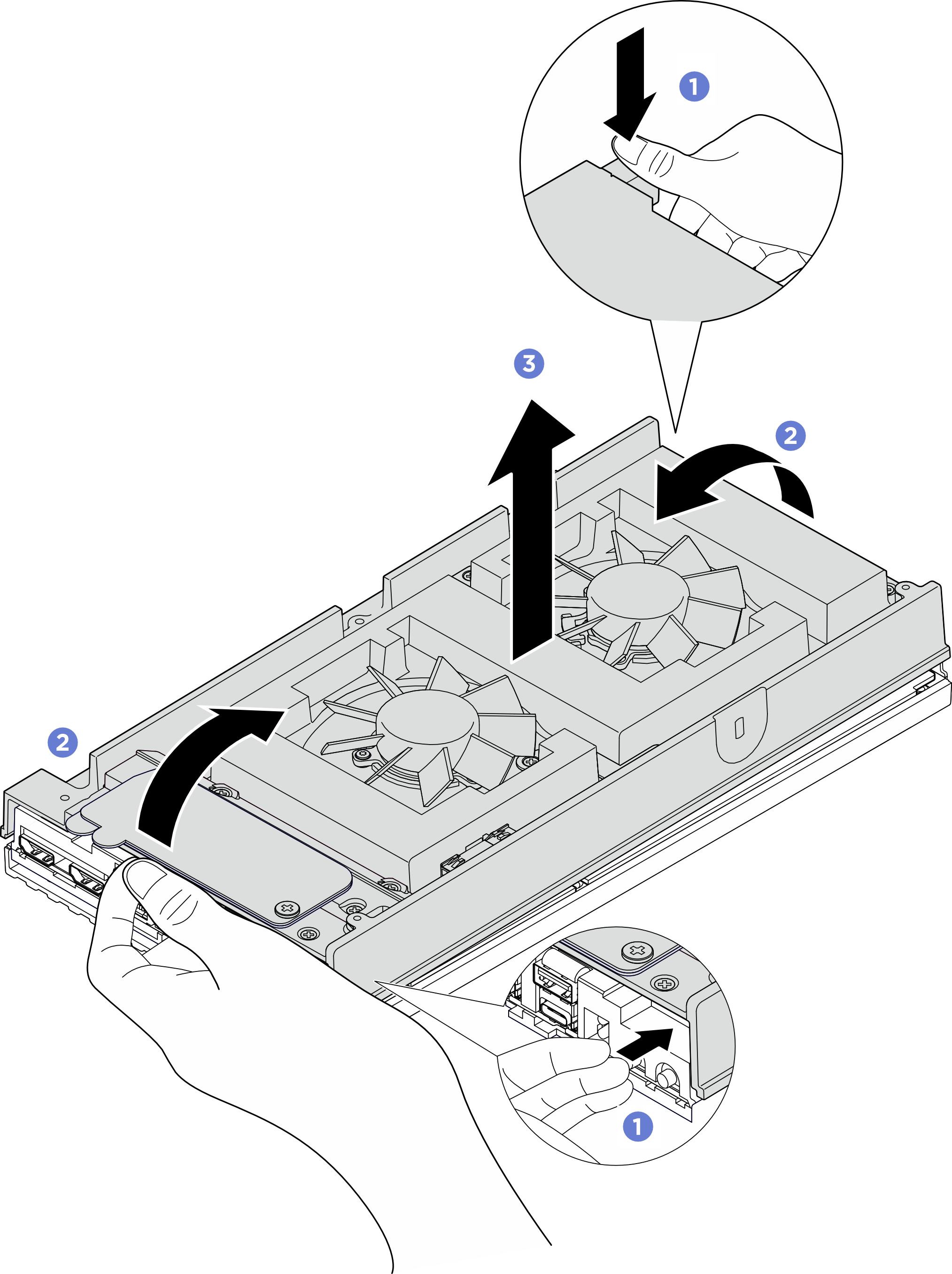
- Remove the top cover.
- Pinch the tab on the rear of the node, and hold the front side of the node by its edge. Insert your fingers into the hole on the front of the node as illustrated.
- While pressing the tab to keep the node stable, separate the front side of top cover from the node. Then, separate the rear side of top cover from the node.
- Remove the top cover from the node and place the top cover on a flat clean surface.AttentionTo make sure that there is adequate system cooling, install both top cover and bottom cover before powering on the server. Operating the server with the covers removed might damage server components.Figure 3. Removing the top cover
Install a replacement unit. See Install the top cover.
If you are instructed to return the component or optional device, follow all packaging instructions, and use any packaging materials for shipping that are supplied to you.
Demo video