Install the fan bridge cable
Follow instructions in this section to install a fan bridge cable.
About this task
S002
CAUTION
The power-control button on the device and the power switch on the power supply do not turn off the electrical current supplied to the device. The device also might have more than one power cord. To remove all electrical current from the device, ensure that all power cords are disconnected from the power source.
S017

CAUTION
Hazardous moving fan blades nearby. Keep fingers and other body parts away.
Attention
Read Installation Guidelines and Safety inspection checklist to ensure that you work safely.
Touch the static-protective package that contains the component to any unpainted metal surface on the server; then, remove it from the package and place it on a static-protective surface.
Procedure
- Locate the fan bridge cable to be installed.
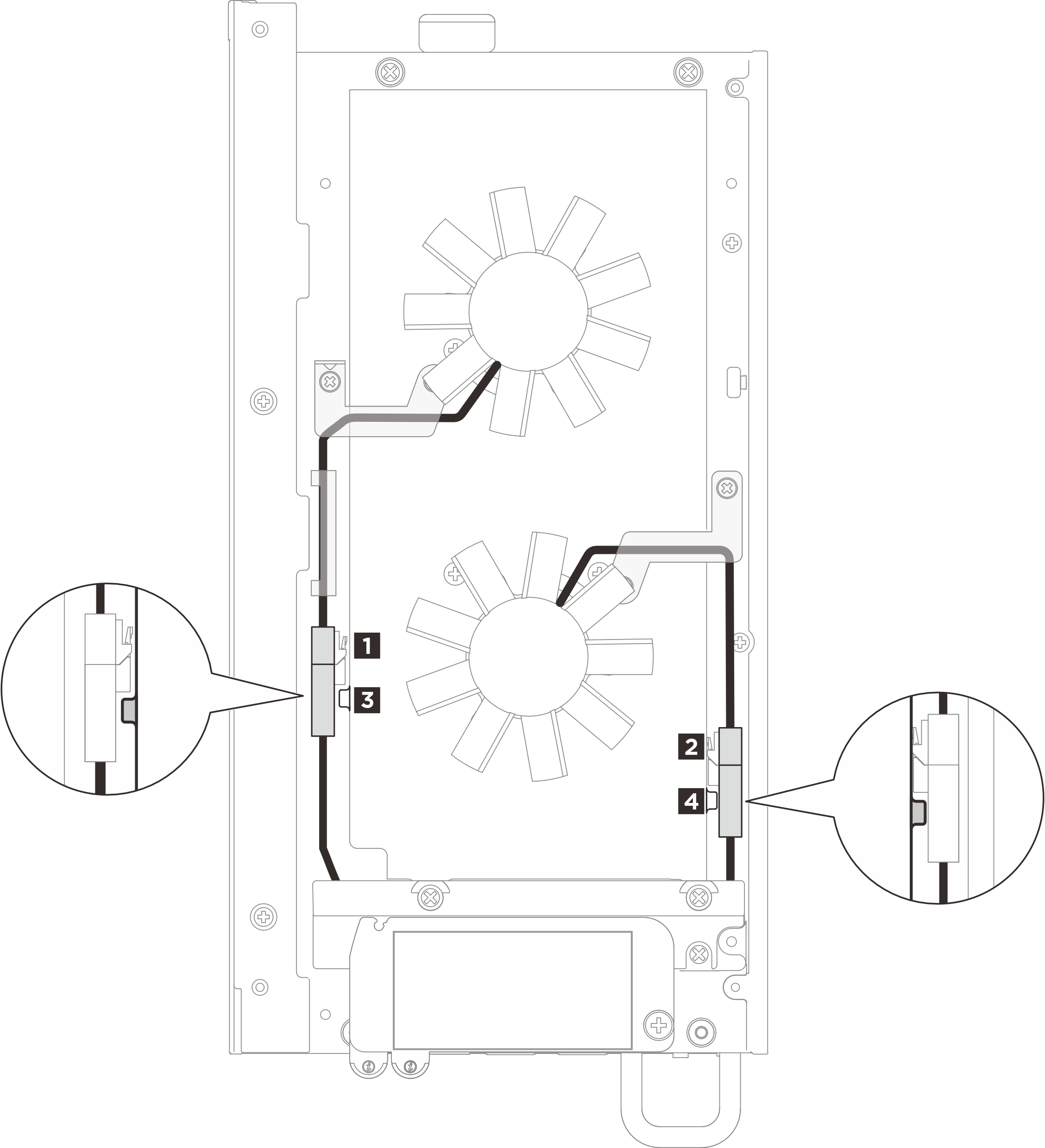
1 Cable of Fan module 1 2 Cable of Fan module 2 3 Fan bridge cable 1 3 Fan bridge cable 2 - Install the fan bridge cable to the node.
- Insert the fan bridge cable to the connector hole; then push the fan bridge cable to the right (viewed from the front of the node) until it locks into place.Figure 1. Installing the fan bridge cable
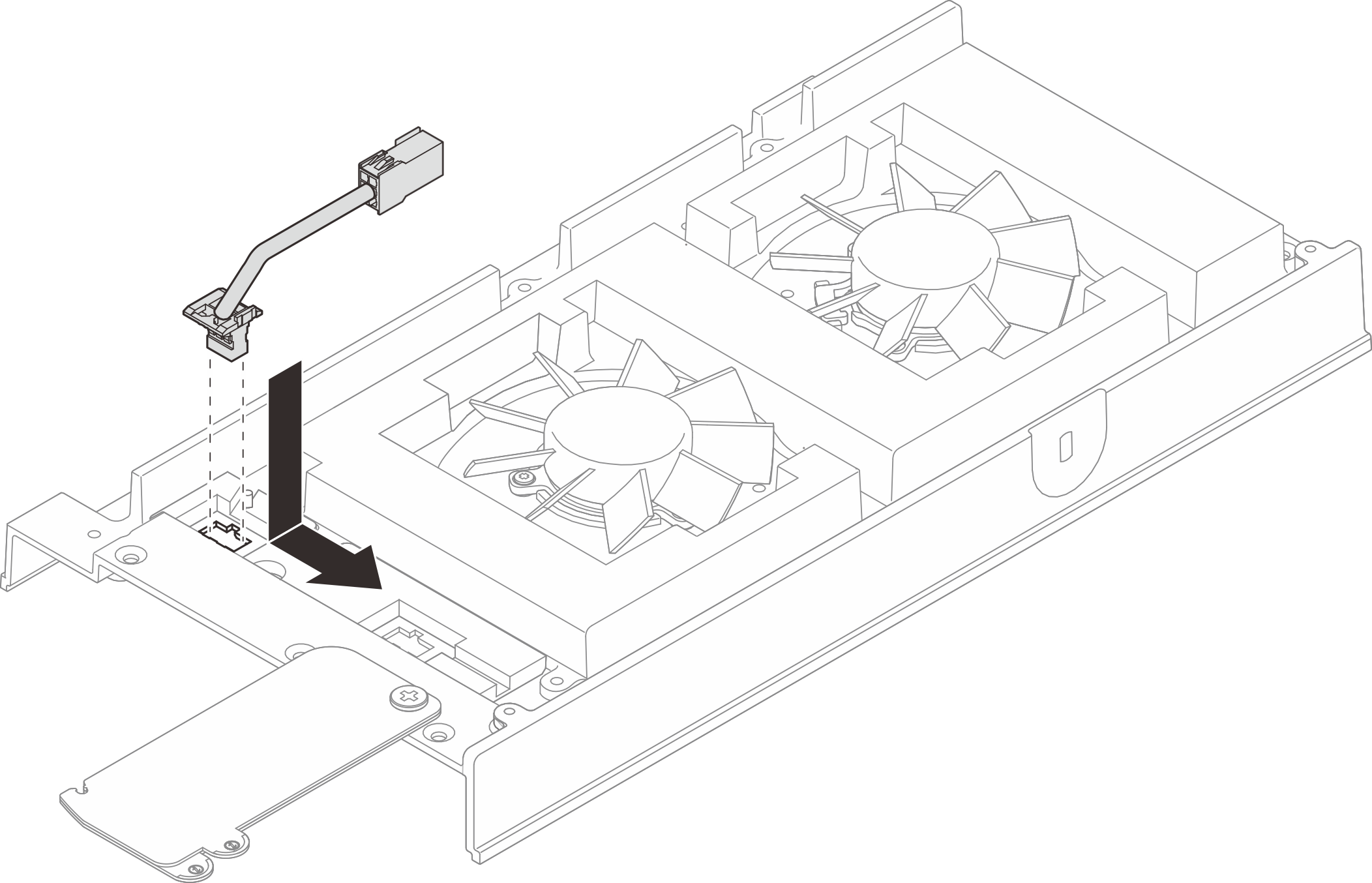
- Insert the fan bridge cable to the connector hole; then push the fan bridge cable to the right (viewed from the front of the node) until it locks into place.
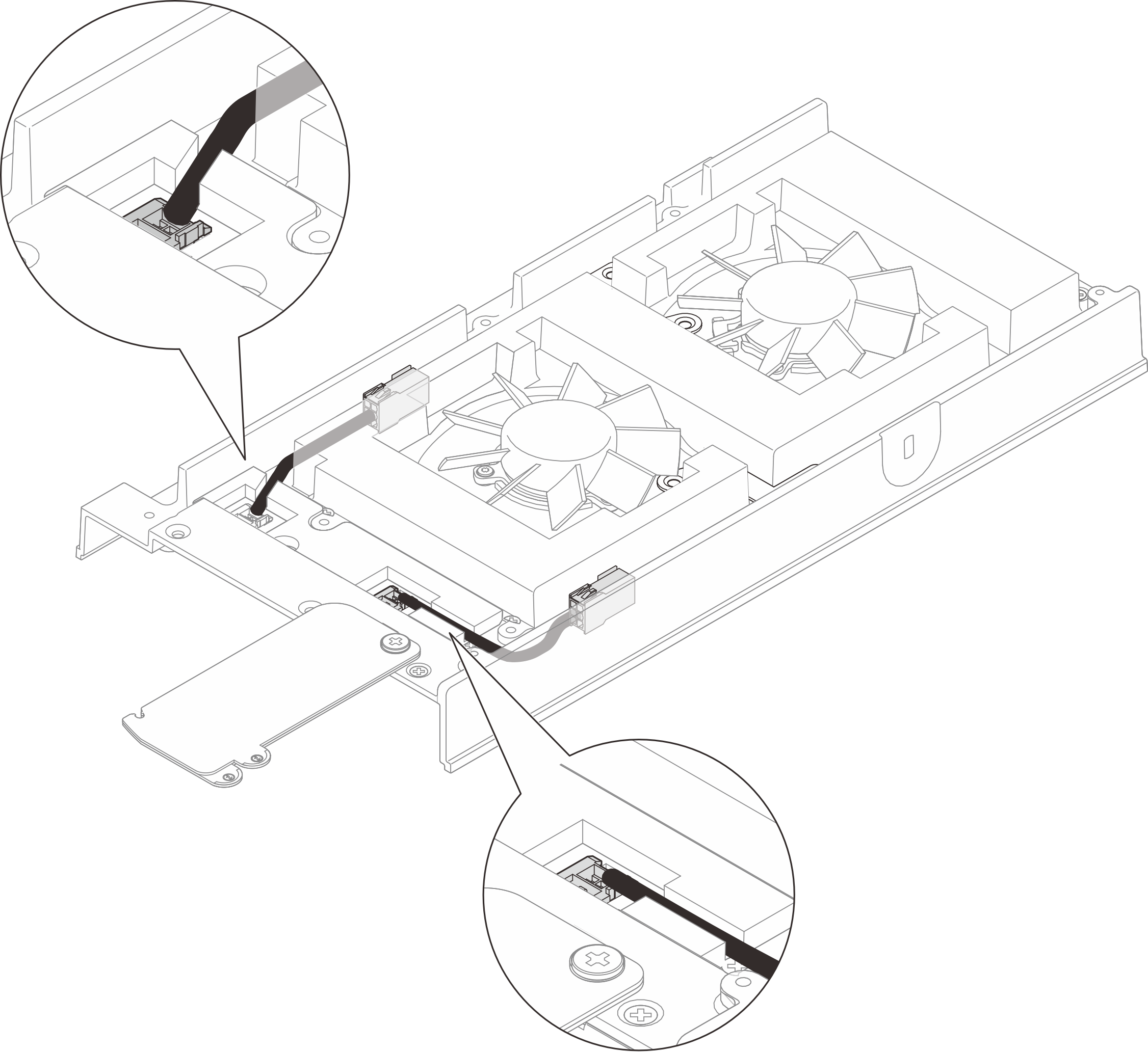
- Route the cable through the pre-cut slot on the node.Figure 2. Fan bridge cables
- Install the fan bridge cable cover.
 Align the fan bridge cable cover with the screw slots on the node; then, tighten four screws to secure the fan bridge cable cover.
 Slide the pull-out information tabs towards the node.Figure 3. Installing the fan bridge cable cover
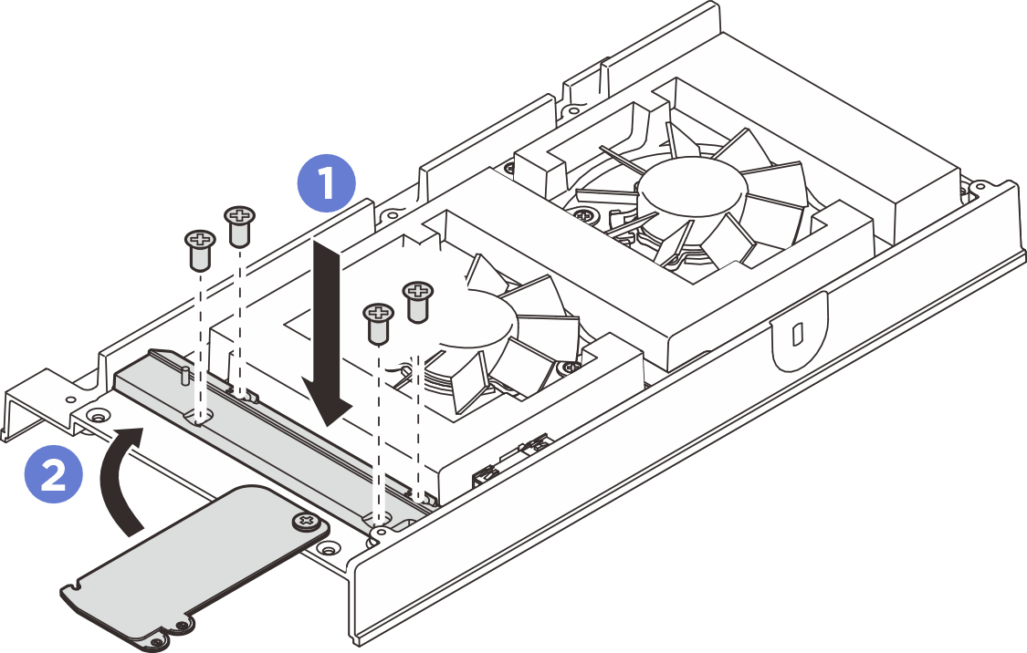
- There are labels attached on fan bridge cables and fan module cables. Before routing the cables, roll the label around the cable all the way through.Figure 4. Rolling label around the cable

- Press the cables with rolled labels into the cable slot on top cover as illustrated. Make sure the cable of Fan module 1 is secured between the foam and the chassis.Figure 5. Fan cable routing
 NoteMake sure to press the connectors into the slot to avoid interfering with the fan shroud.
After you finish
- Install the top cover. See Install the top cover.
- If applicable, install the expansion filler. See Install the expansion filler.
- If applicable, install the expansion kit. See Install the expansion kit.
- Install the fan shroud. See Install the fan shroud.
- Complete the parts replacement. See Complete the parts replacement.
Demo video
Give documentation feedback