10 x 2.5'' NVMe
Use this section to understand the cable routing of 10 NVMe front drives.
To connect power cables for a backplane for standard 2.5-inch or 3.5-inch drives, refer to Cable routing for backplane power.
To connect cables for M.2 drives, refer to M.2 drive backplane.
Cable routing for onboard configuration
The following illustrations and tables show the mapping relationship between backplane connectors and processor board connectors for onboard configuration.
The following figure illustrates the cable routing for the configuration of 10 front SAS/SATA drives bays. Connections between connectors: 1 ↔ 1, 2 ↔ 2, 3 ↔ 3, ... n ↔ n.
Note
Depending on the type of cable, there are two ways to route the cables for onboard configuration of 10 x 2.5 NVMe front drives.
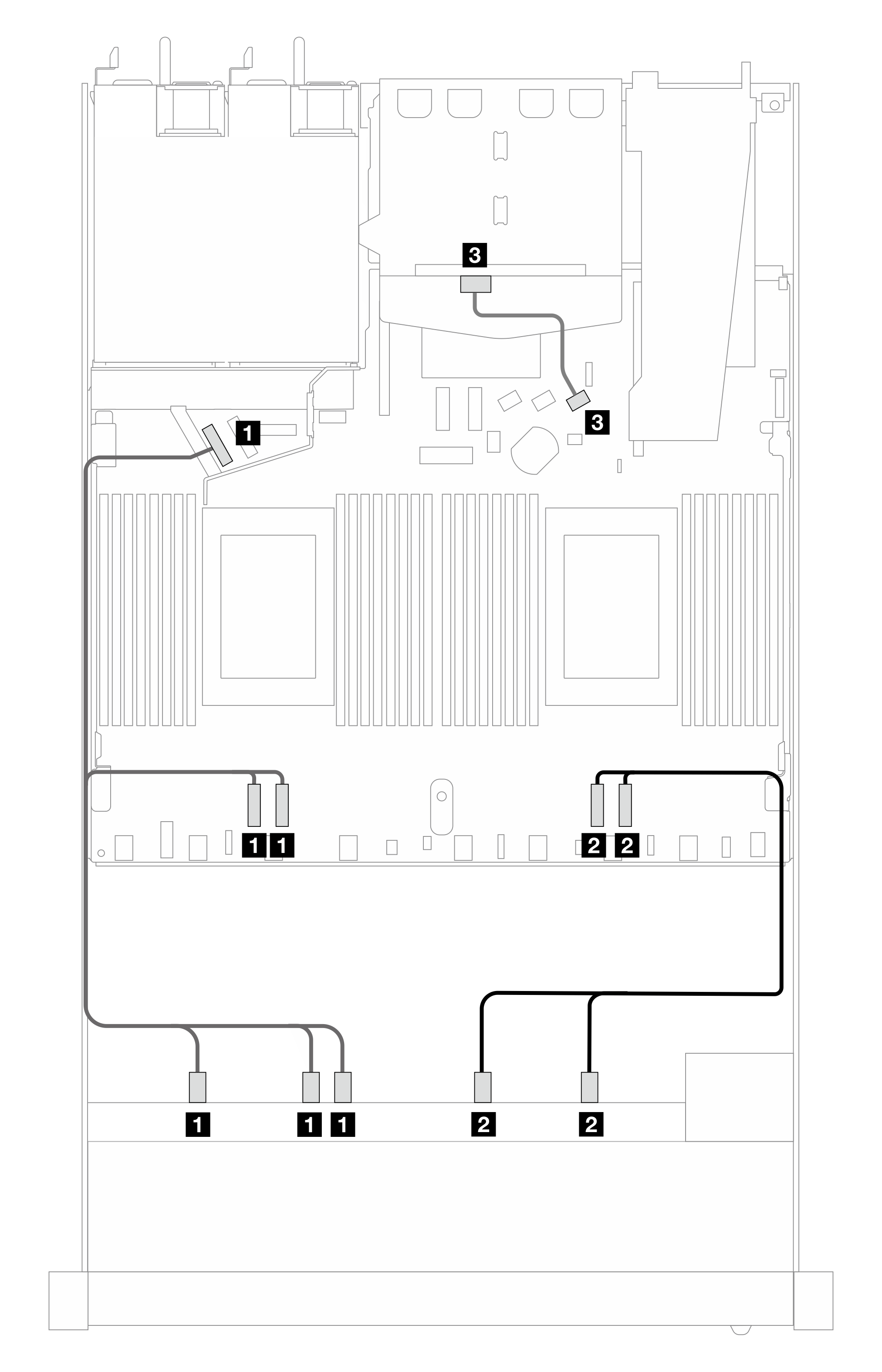
Figure 1. Cable routing for onboard configuration of 10 x 2.5 NVMe front drives

| Backplane | From | To |
|---|---|---|
| Front BP (NVMe) | 1 NVMe 2–3, NVMe 0–1, NVMe 4–5 | 1 PCIe 3, PCIe 4, PCIe 5 |
| 2 NVMe 8–9, NVMe 6–7 | 2 PCIe 1, PCIe 2 |
Figure 2. Cable routing for onboard configuration of 10 x 2.5 NVMe front drives
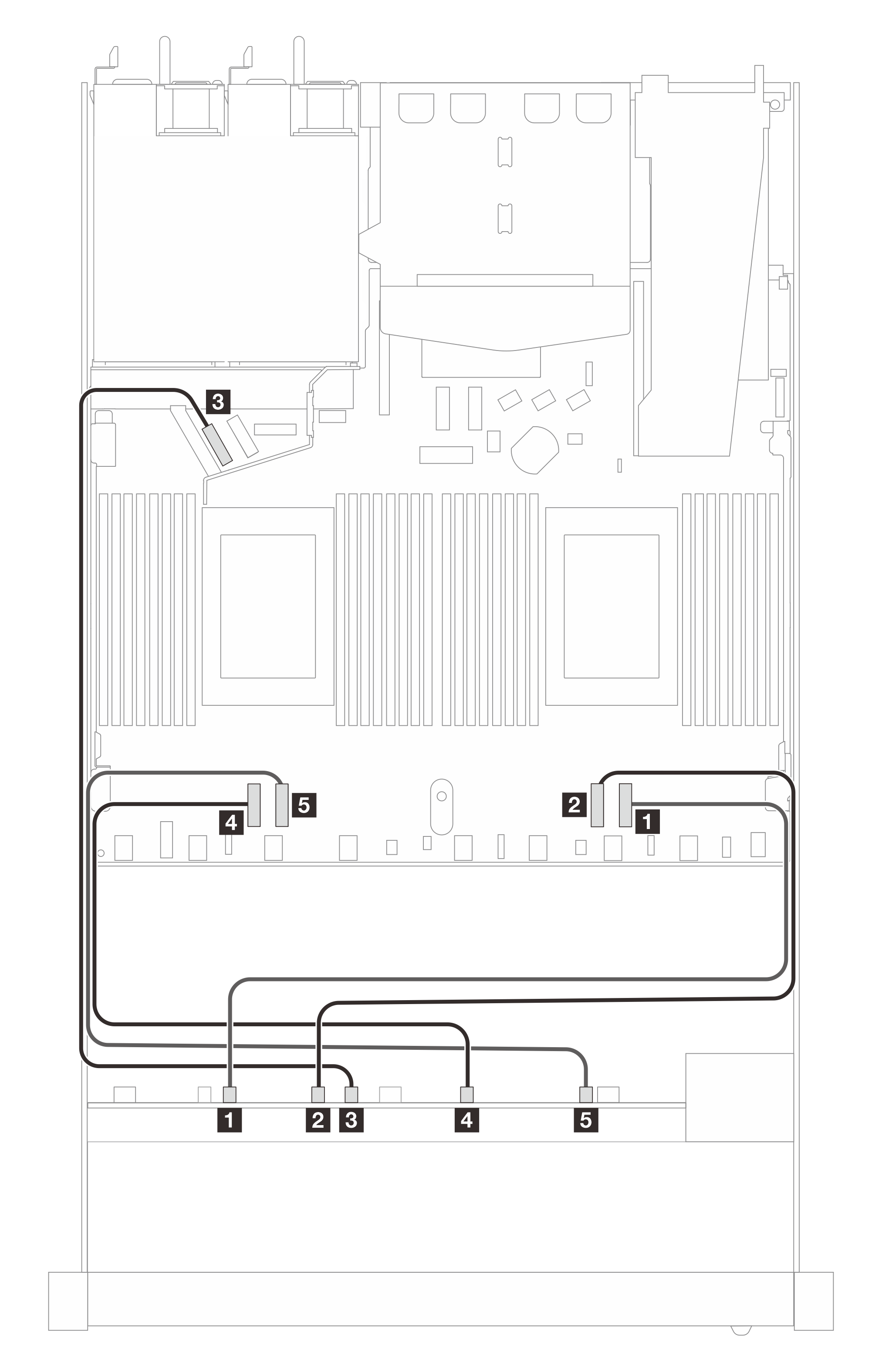
| Backplane | From | To |
|---|---|---|
| Front BP (NVMe) | 1 NVMe 0–1 | 1 PCIe 1 |
| 2 NVMe 2–3 | 2 PCIe 2 | |
| 3 NVMe 4–5 | 3 PCIe 5 | |
| 4 NVMe 6–7 | 4 PCIe 4 | |
| 5NVMe 8–9 | 5 PCIe 3 |
Figure 3. Cable routing for onboard configuration of 10 x 2.5 NVMe front drives with 2 x 2.5 rear SAS/SATA drives installed
| Backplane | From | To |
|---|---|---|
| Front BP (NVMe) | 1 NVMe 2–3, NVMe 0–1, NVMe 4–5 | 1 PCIe 3, PCIe 4, PCIe 5 |
| 2 NVMe 8–9, NVMe 6–7 | 2 PCIe 1, PCIe 2 | |
| Rear BP (SAS) | 3 SAS (rear) | 3 SATA 2 |
Give documentation feedback