4 x 2.5'' NVMe backplane (one processor)
Use this section to understand the NVMe backplane cable routing for server model with four 2.5-inch front drives.
To connect cables for a 7mm drive backplane, refer to 7mm drive backplane.
To connect power cables for a backplane for standard 2.5-inch or 3.5-inch drives, refer to Cable routing for backplane power.
Cable routing for onboard configuration with one processor
The following table shows the mapping relationship between backplane connectors and processor board connectors for onboard configuration.
The following figure illustrates the cable routing for the onboard configuration of 4 x 2.5-inch front NVMe drive bays. Connections between connectors: 1 ↔ 1, 2 ↔ 2, 3 ↔ 3, ... n ↔ n
Figure 1. Cable routing for onboard configuration of 4 x 2.5-inch front NVMe drive bays with one processor
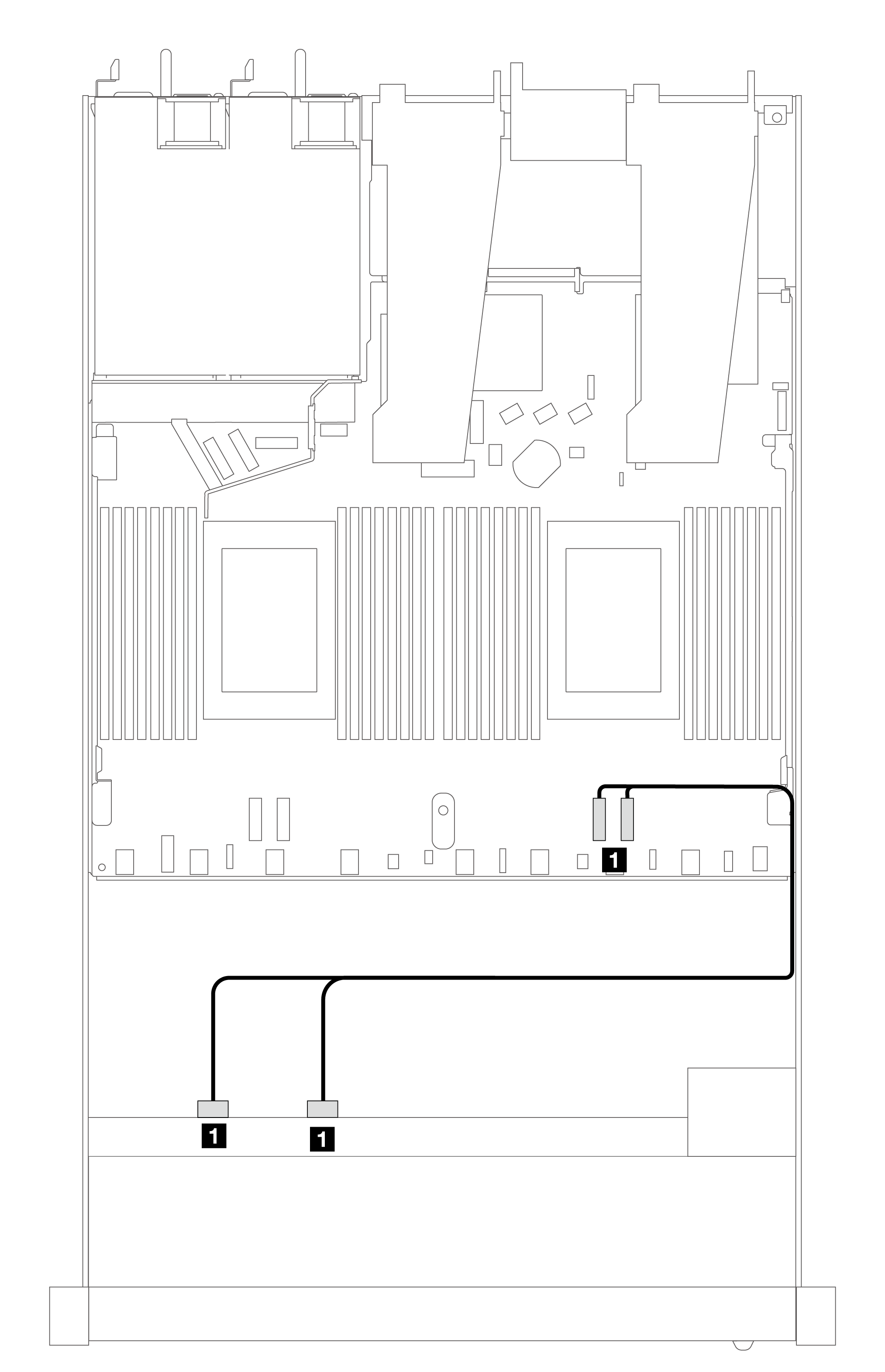
| Backplanes | From | To |
|---|---|---|
| Front BP (NVMe) | NVMe 2–3, NVMe 0–1 | PCIe 1, PCIe 2 |
Figure 2. Cable routing of 4 x 2.5-inch front NVMe drive bays and a re-timer adapter (Gen 4) with one processor
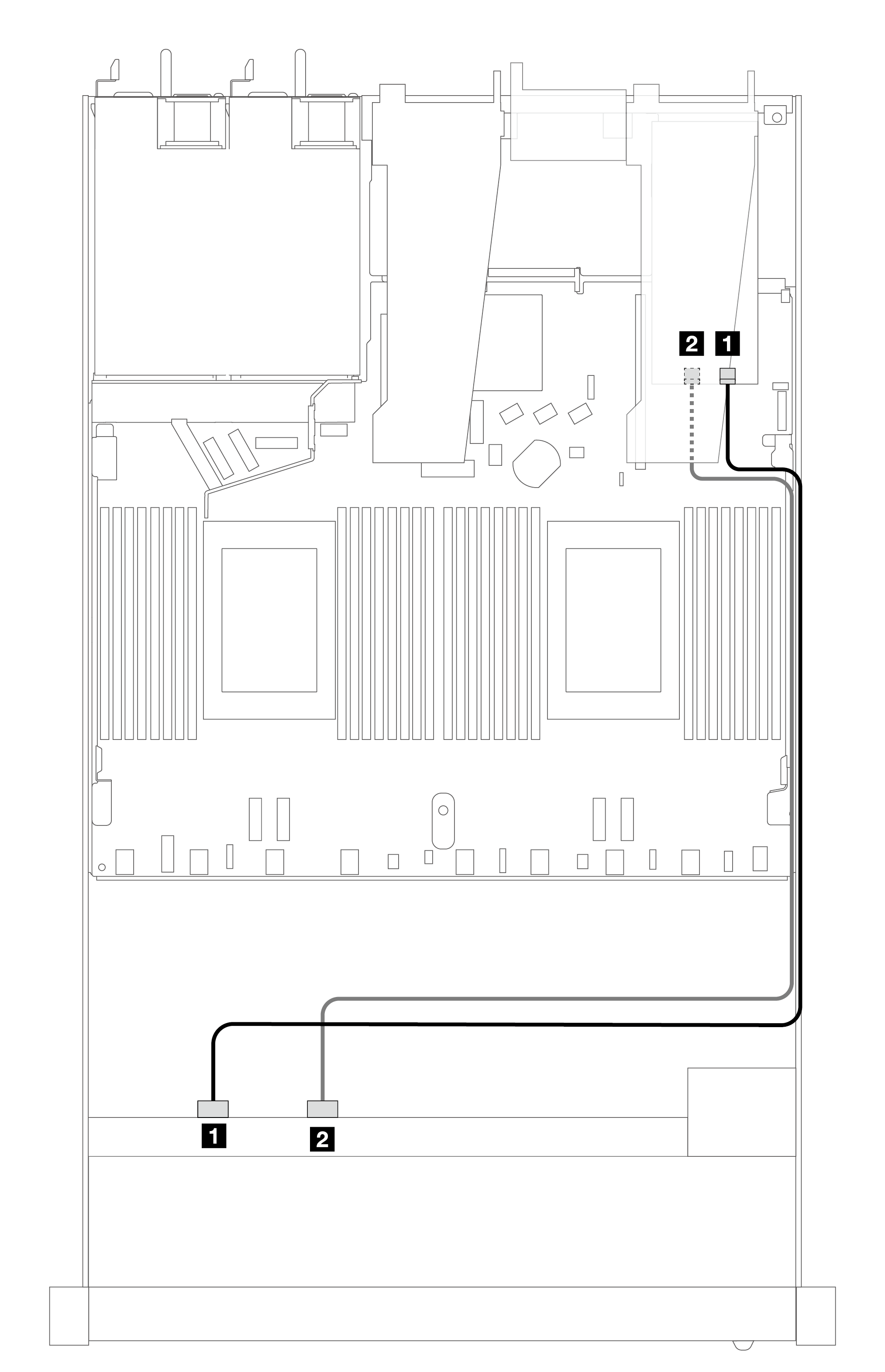
| Backplanes | From | To |
|---|---|---|
| Front BP (NVMe) | NVMe 0–1, NVMe 2–3 | C0, C1 |
Give documentation feedback