4 x 3.5'' SAS/SATA backplane (one processor)
Use this section to understand the SAS/SATA backplane cable routing for server model with four 3.5-inch front drives.
To connect cables for a 7mm drive backplane, refer to 7mm drive backplane.
To connect power cables for a backplane for standard 2.5-inch or 3.5-inch drives, refer to Cable routing for backplane power.
To connect cables for M.2 drives, refer to M.2 drive backplane.
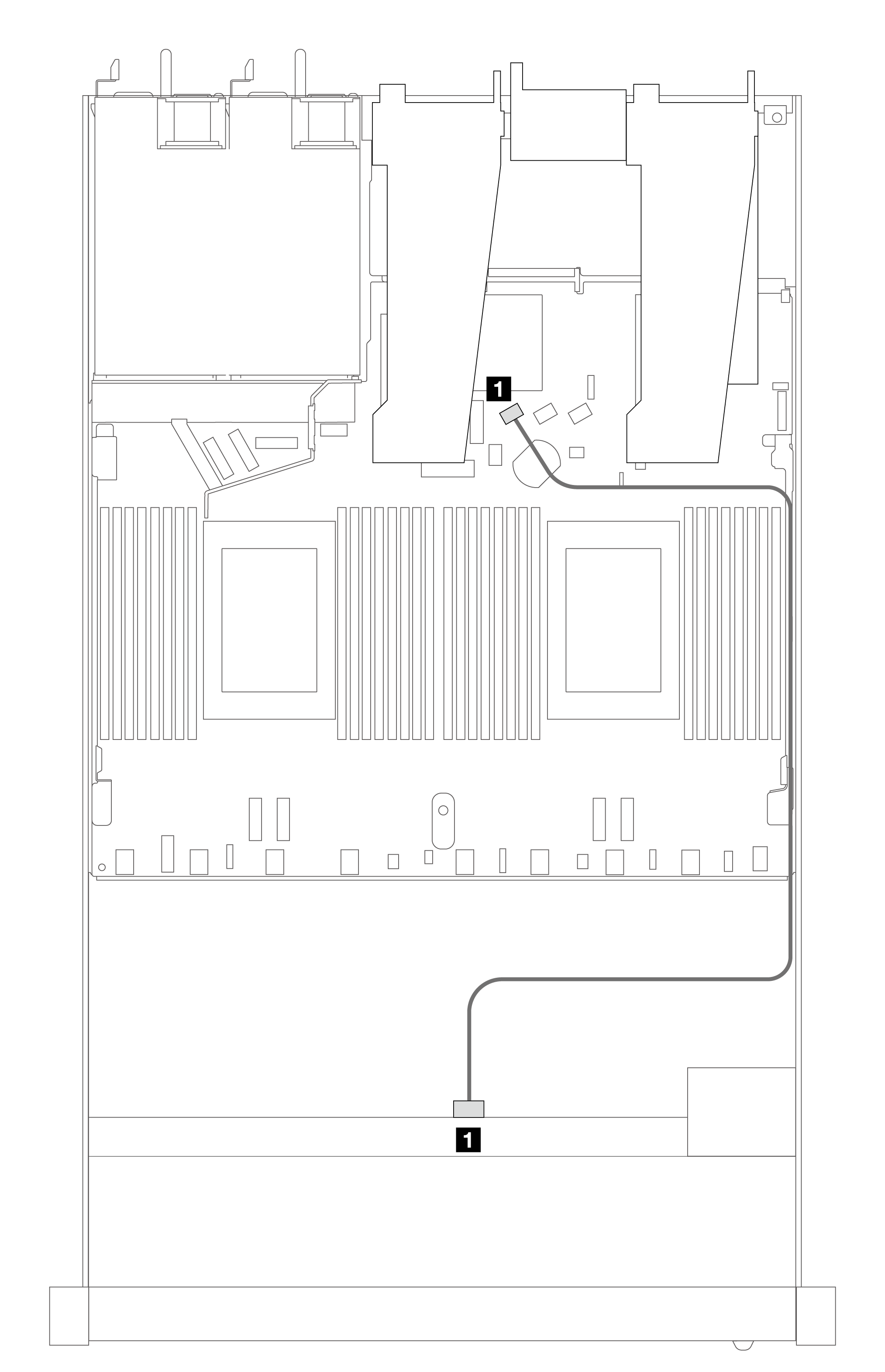
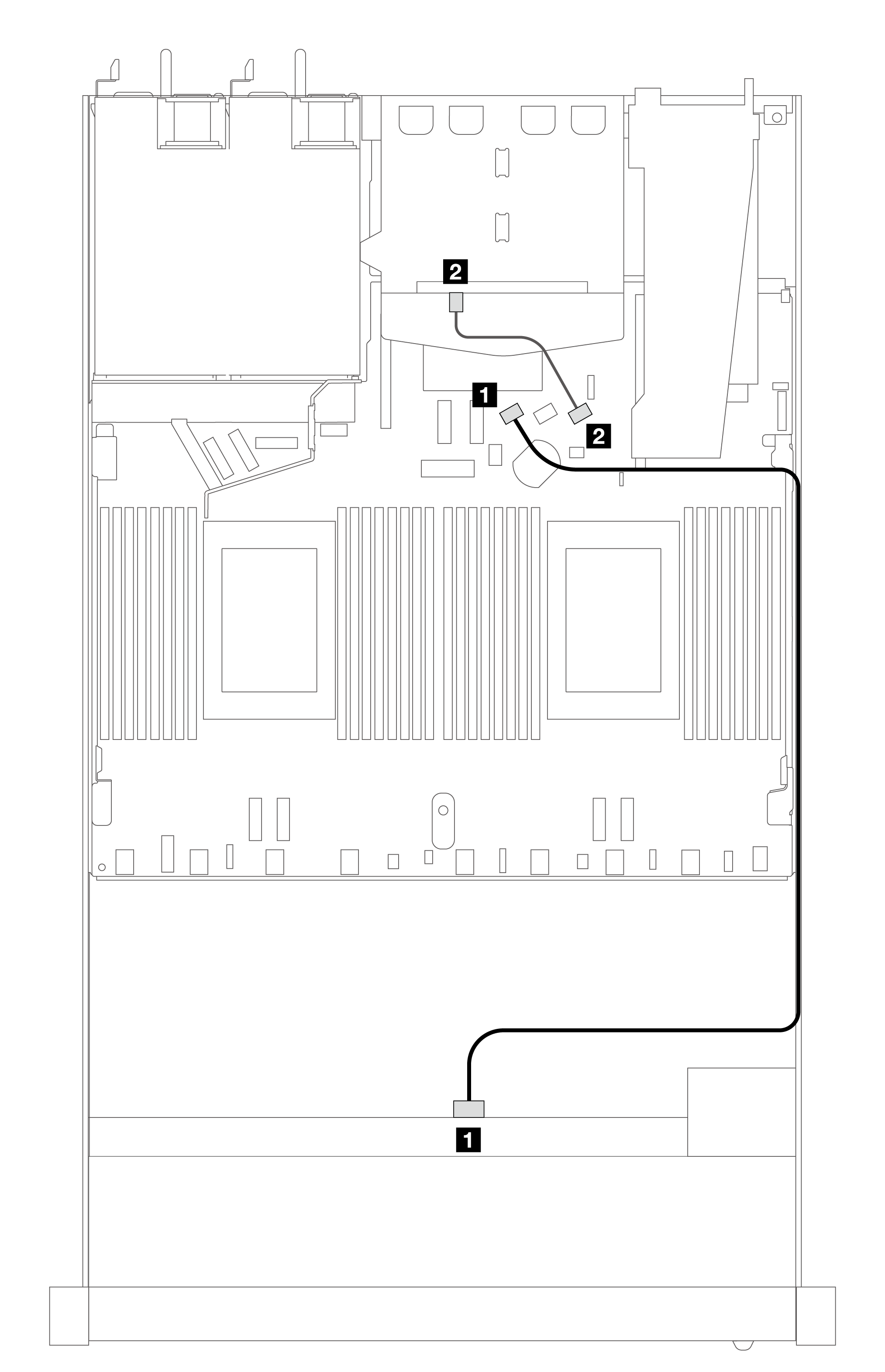
Cable routing for onboard configuration
The following table shows the mapping relationship between backplane connectors and processor board connectors for onboard configuration.
The following figure illustrates the cable routing for the onboard configuration of 4 x 3.5-inch front SAS/SATA drive bays. Connections between connectors: 1 ↔ 1, 2 ↔ 2, 3 ↔ 3, ... n ↔ n.
| Backplane | From | To |
|---|---|---|
| 1 Front BP (SAS) | SAS | SATA 0 |
| Backplane | From | To |
|---|---|---|
| 1 Front BP (SAS) | SAS (front) | SATA 0 |
| 2 Rear BP (SAS) | SAS (rear) | SATA 2 |
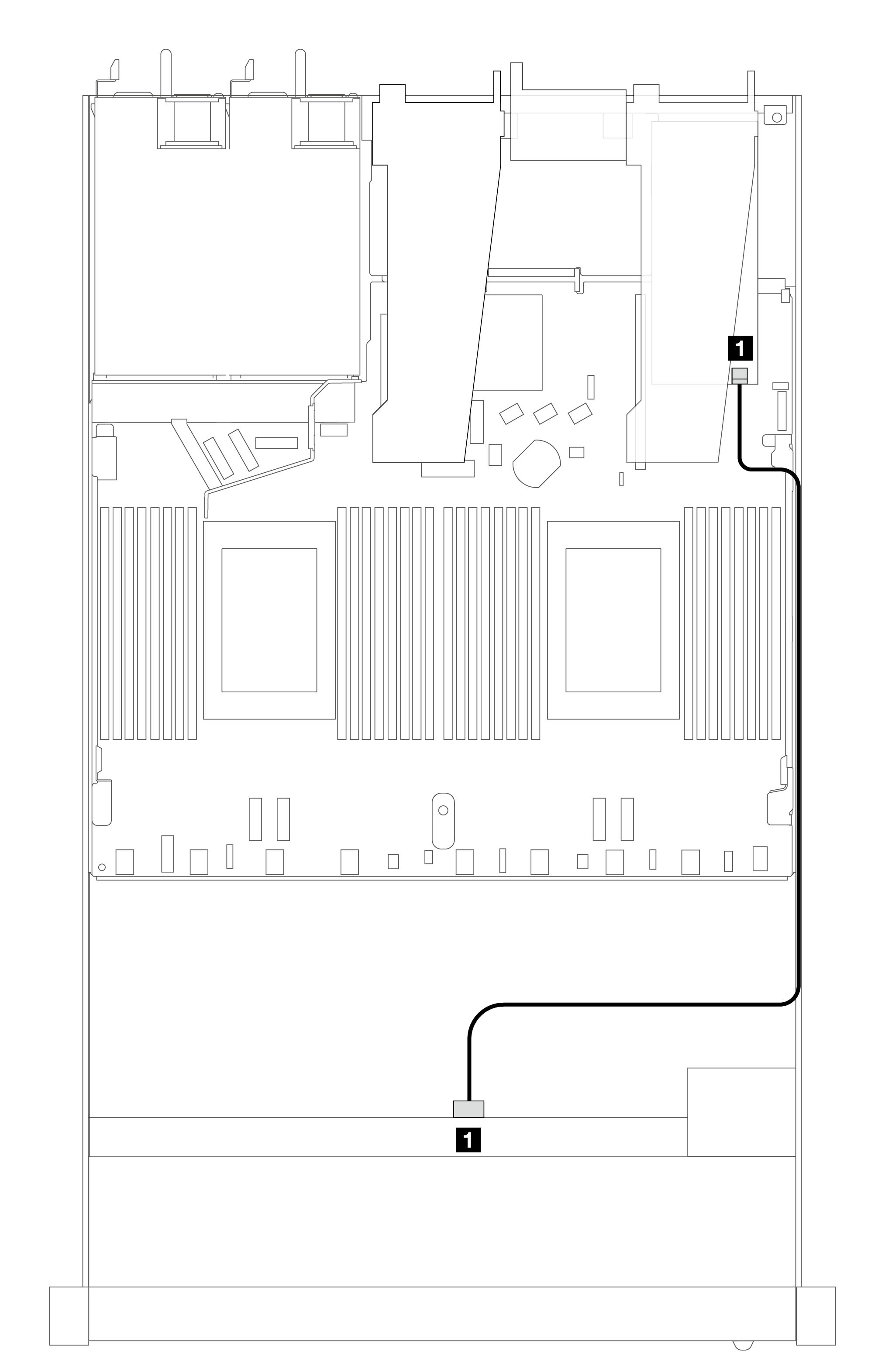
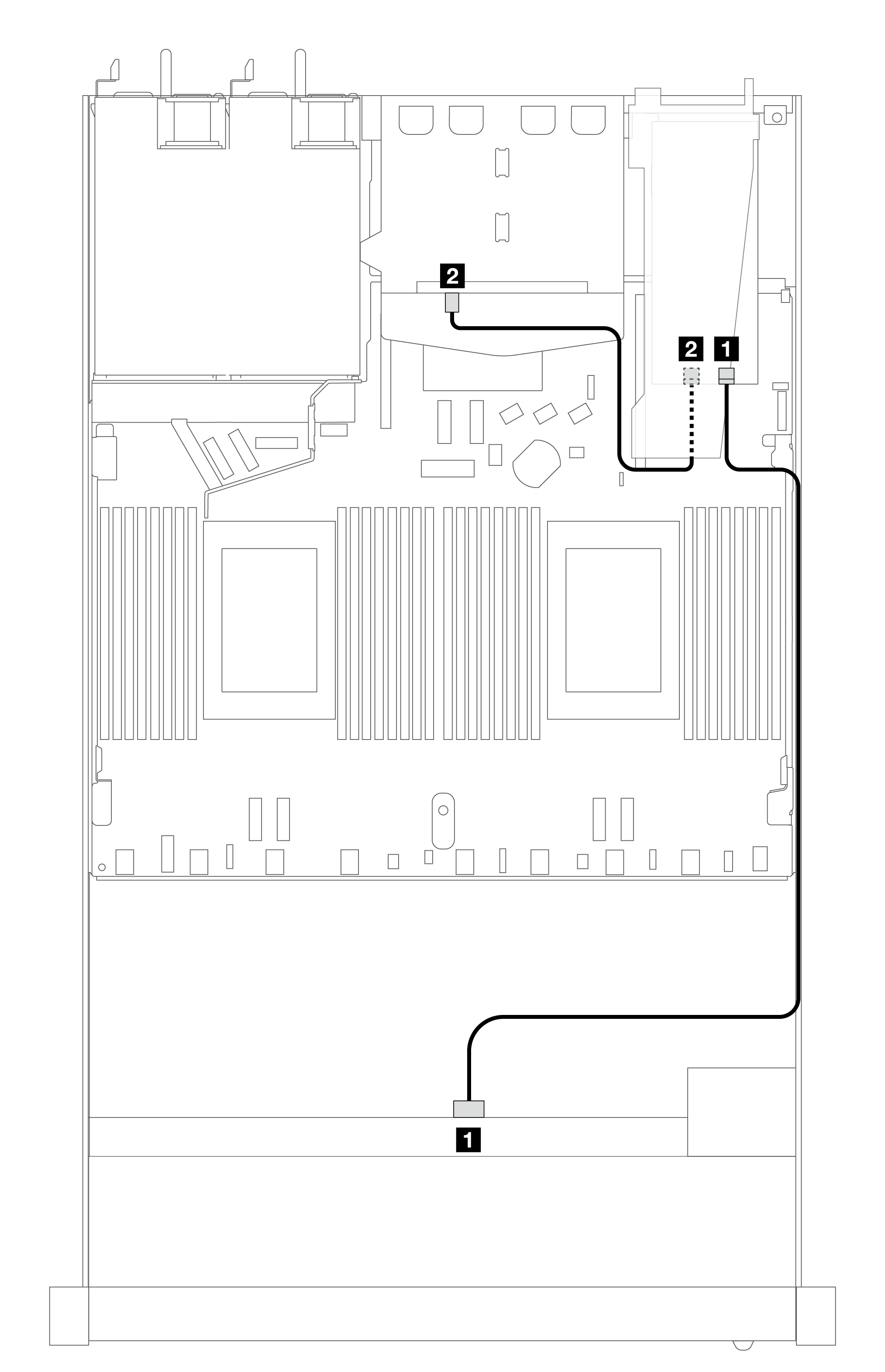
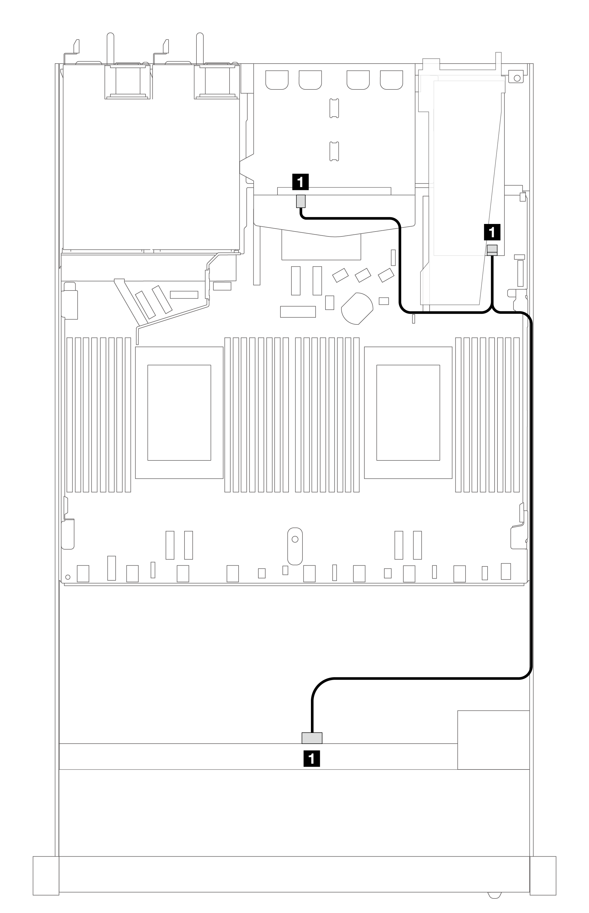
Cable routing with an SFF HBA/RAID adapter
The following table shows the mapping relationship between backplane connectors and processor board/adapter connectors when an 8i SFF HBA/RAID adapter (Gen 3 or Gen 4) is installed.
The following figure illustrates the cable routing for the configuration of 4 x 3.5-inch front SAS/SATA drive bays with an 8i SFF RAID adapter. Connections between connectors: 1 ↔ 1, 2 ↔ 2, 3 ↔ 3, ... n ↔ n.
| Backplane | From | To |
|---|---|---|
| 1 Front BP (SAS) | SAS | C0 |
Gen 3 and Gen 4 SFF HBA/RAID adapters are slightly different in their connectors, but the cable routing method is similar.
To connect cables for RAID flash power module, refer to RAID flash power modules.
The following table shows the mapping relationship between backplane connectors and processor board/adapter connectors when an 8i SFF HBA/RAID adapter (Gen 3) is installed.
| Backplane | From | To |
|---|---|---|
| 1 Front BP (SAS) | SAS | C0 |
| 2 Rear BP (SAS) | SAS (rear) | C1 |
The following table shows the mapping relationship between backplane connectors and processor board/adapter connectors when an 8i SFF HBA/RAID adapter (Gen 4) is installed.
| Backplane | From | To |
|---|---|---|
| 1 Front and Rear BP (SAS) | SAS | C0 |