Install the Lenovo Neptune Liquid to Air Module
Follow the instructions in this section to install the Liquid to Air Module (L2AM).
This task must be operated by trained technicians that are certified by Lenovo Service. Do not attempt to remove or install the part without proper training and qualification.
About this task

Read Installation Guidelines and Safety inspection checklist to ensure that you work safely.
Power off the server and peripheral devices and disconnect the power cords and all external cables. See Power off the server.
Prevent exposure to static electricity, which might lead to system halt and loss of data, by keeping static-sensitive components in their static-protective packages until installation, and handling these devices with an electrostatic-discharge wrist strap or other grounding systems.
| Torque screwdriver type list | Screw Type |
|---|---|
| Torx T30 head screwdriver | Torx T30 screw |
Procedure
- Prepare your server.
- Install the leakage detection sensor module holder to the chassis.
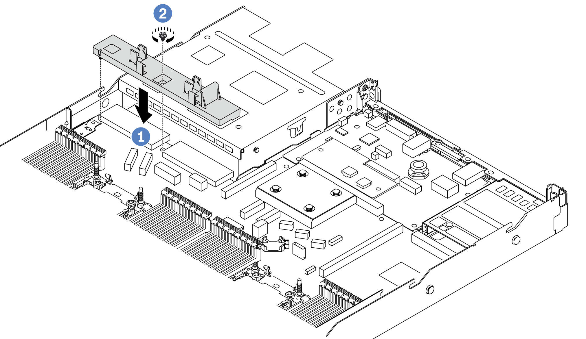
 Align the leakage detection sensor module holder to the corresponding screw hole on the chassis.
 Tighten the screw and ensure that the holder is secured in place.
- Install the radiator tray to the chassis.
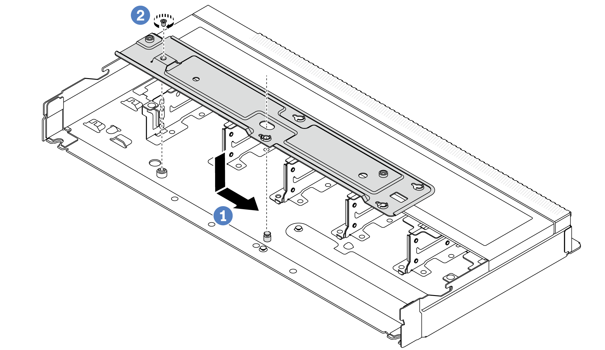
- Place the tray evenly into the chassis and then move it to the right so that the screw hole on the tray aligns with the hole on the chassis.
- Tighten the screw.
- Install the leakage detection sensor module holder to the chassis.
- Separate the L2AM module from the shipping tray.
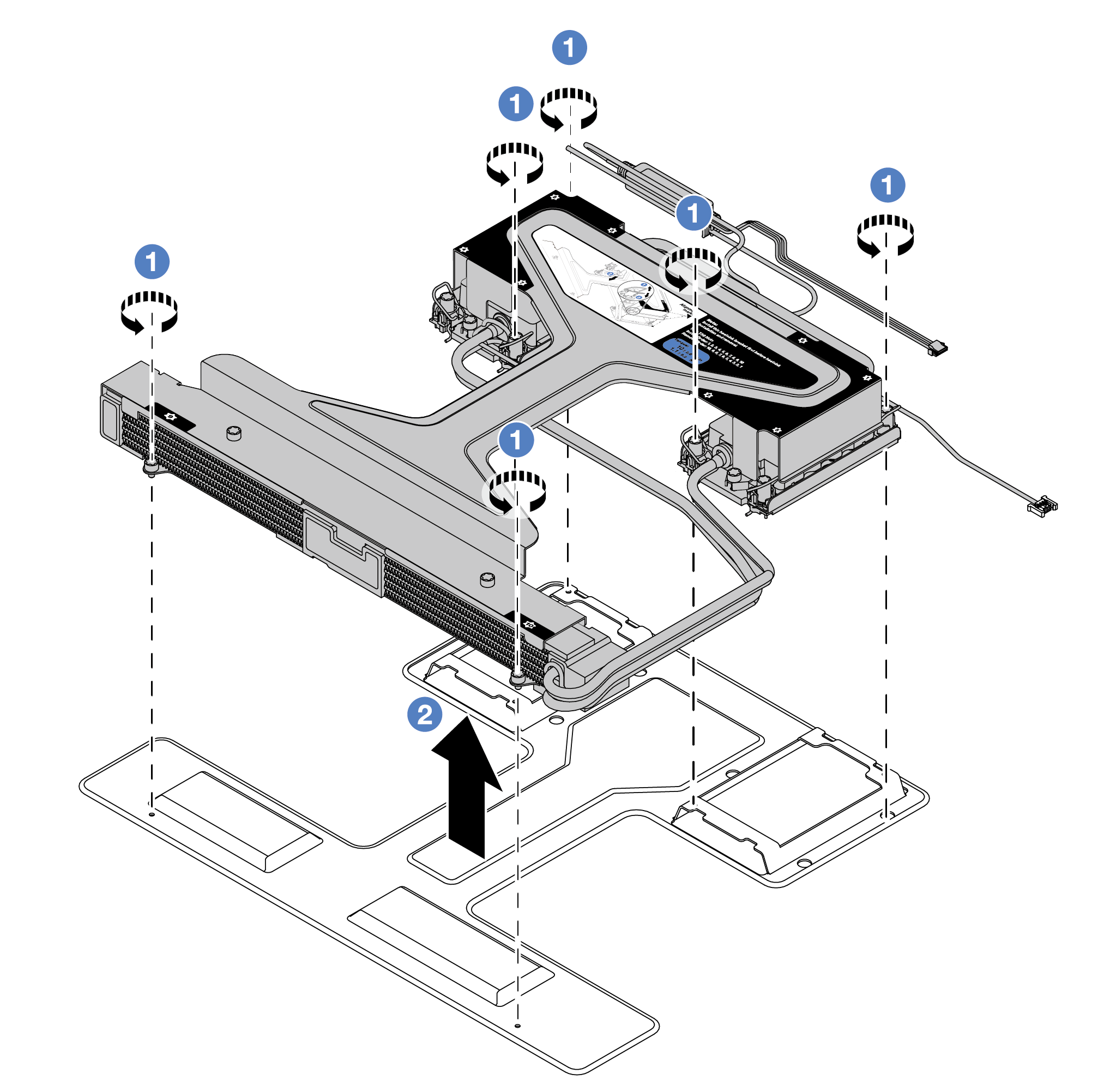
- Loosen the six screws on the L2AM module shipping tray.
- Lift the L2AM by the module handle (L2AM heat sink bracket) to separate the module from the shipping tray.
- Install the processor to the L2AM.
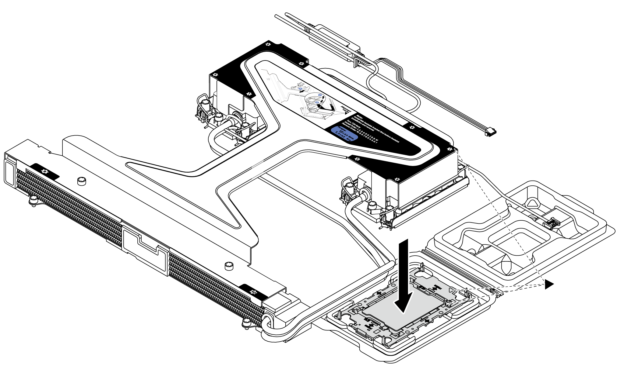
Align the triangular mark on the cold plate assembly label with the triangular mark on the processor carrier and processor.
Install the L2AM onto the processor-carrier.
Press the carrier into place until the clips at all four corners engage.
NoteIf your server only has one processor installed, generally processor 1, it is required to install a cover to the empty socket of processor 2 before proceeding with further installation.Figure 1. Install the processor socket cover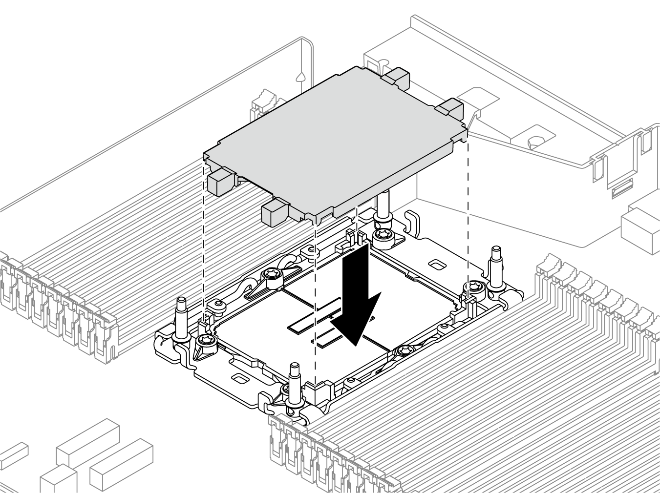
- Install the processor-L2AM to the system board assembly.
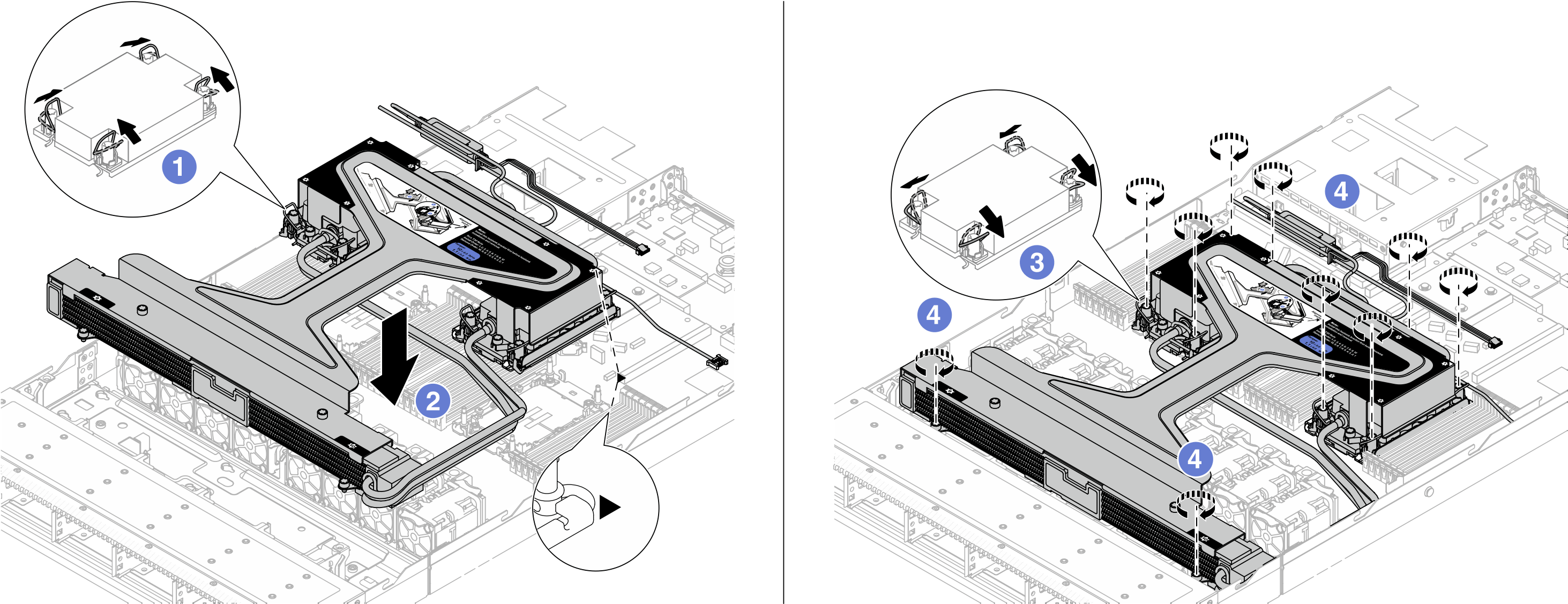
- Rotate the anti-tilt wire bails inward.
- Align the triangular mark and four Torx T30 nuts on the cold plate assembly with the triangular mark and threaded posts of the processor socket; then, insert the cold plate assembly into the processor socket.
 Rotate the anti-tilt wire bails outward until they engage with the hooks in the socket.
 Fully tighten the Torx T30 nuts in the installation sequence shown on the cold plate assembly and the radiator. Tighten the screws until they stop; then, visually inspect to make sure that there is no gap between the screw shoulder beneath the cold plate assembly and the processor socket. (For reference, the torque required for the fasteners to fully tighten is 0.9-1.3 newton-meters, 8-12 inch-pounds.)
- Separate the module handle (L2AM heat sink bracket) from the module.
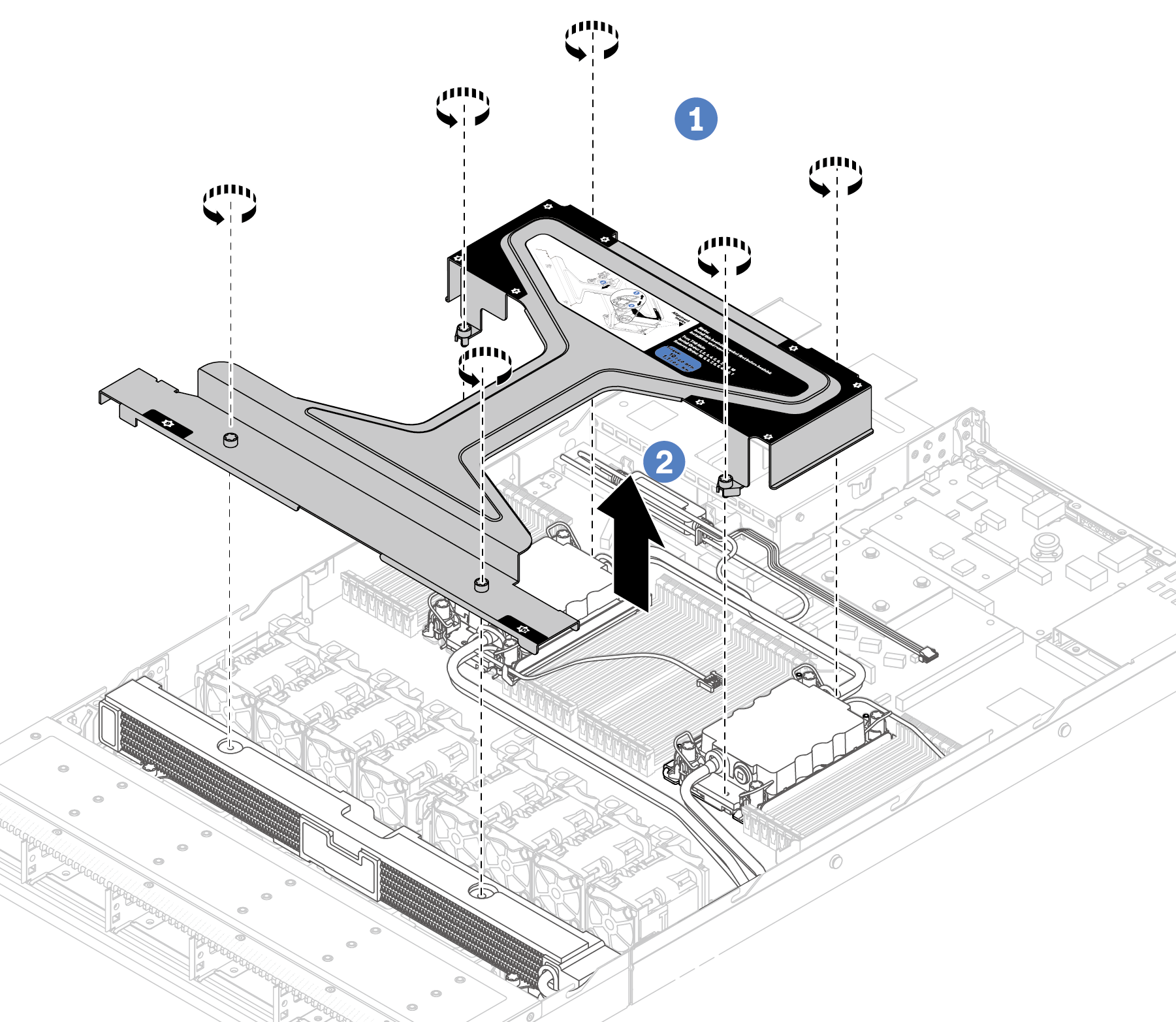
- Loosen the six screws on the module handle (L2AM heat sink bracket).
- Lift the module handle (L2AM heat sink bracket) to separate it from the module.
- Install the leak detection module to the holder.
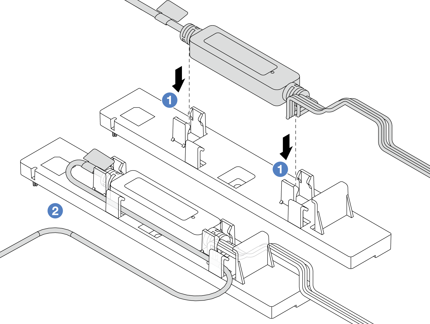 NoteFor
leakage detection sensor module working status, see The LED on the leakage detection sensor module. - Install the leakage detection sensor module into the two clips on the holder. Ensure that the module is secured in place.
- After the module is secured, route the cable through the cable clips to keep tidy for later cable routing arrangements.
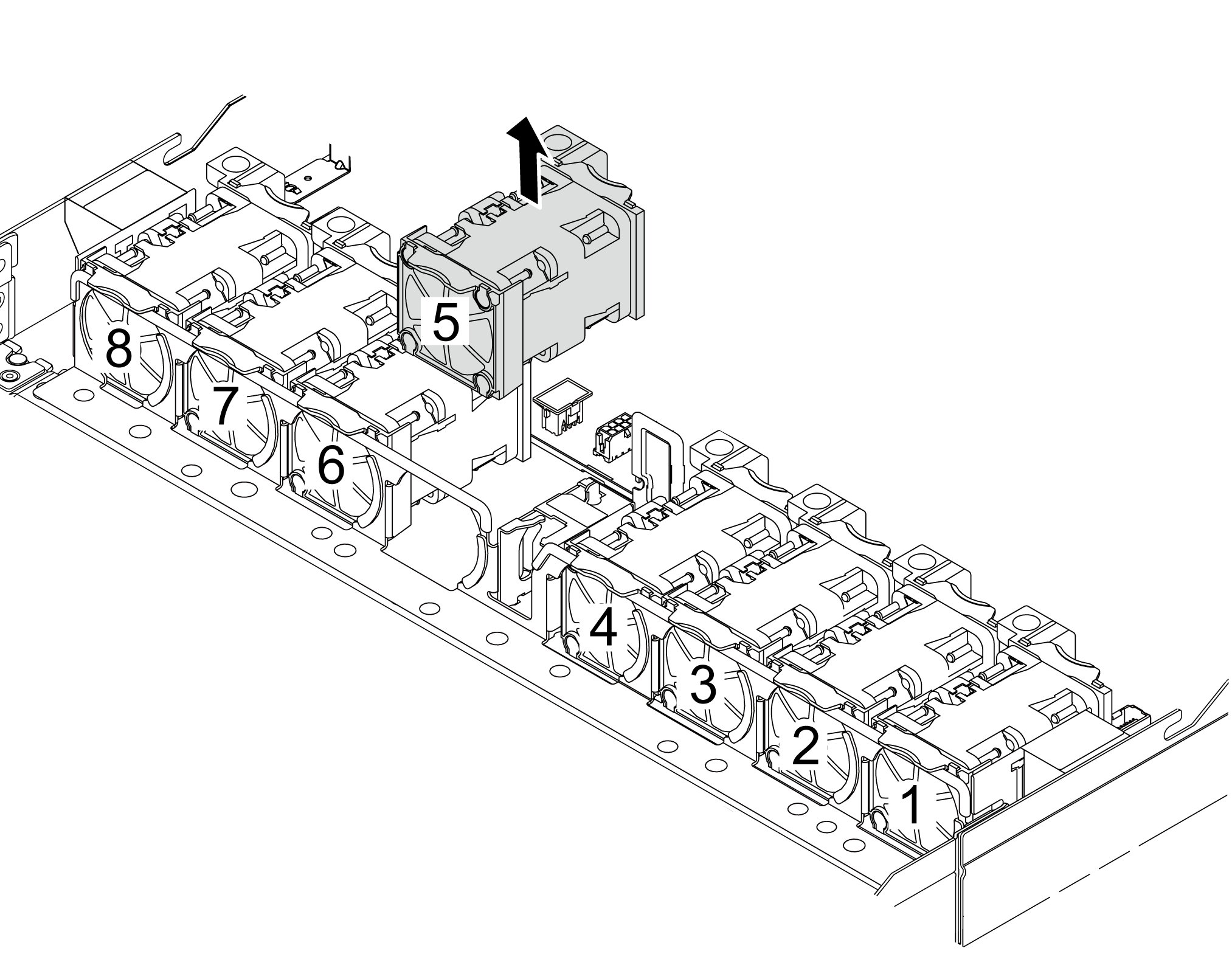
- Remove the system fan 5 from the fan module.
- Re-install the system fan 5 into the fan module.
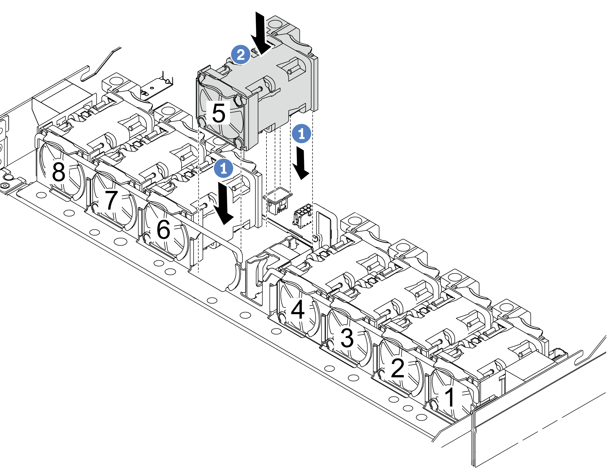
- Align the four corners of the fan to fan module socket and put it down.
- Press the fan latch down to ensure that it is plugged in the connector.