PCIe slots and adapters
Understanding the technical rules for PCIe adapters helps you correctly install and configure PCIe adapters in the system.
PCIe slots supported for different models
| Server rear and front view | Supported types and slot location |
|---|---|
 | Riser 1 assembly
Riser 2 assembly
|
 | Riser 1 assembly
|
 | Riser 1 assembly 1 Slot 1: PCIe 5 (x16), full-height, half-length |
 | Riser 1 assembly
Riser 2 assembly
|
 | Riser 1 assembly
Riser 2 assembly
|
 | Riser 1 assembly 1 Slot 1: PCIe 5 (x16), full-height, half-length |
 | Riser 3 assembly
Riser 4 assembly
|
PCIe adapter installation rules and order
When installing different types of PCIe adapters, refer to the following suggested installation priority:
| Installation priority | |||
|---|---|---|---|
| 1. OCP module | 2. RAID adapter | 3. HBA adapter | 4. GPU adapter |
| 5. InfiniBand adapter | 6. Fibre adapter | 7. Network adapter | 8. Serial port (COM) bracket |
| Adapter type | Recommended slot installation priority | PCIe adapters |
|---|---|---|
| OCP module |
Maximum quantity supported: 2 |
|
Slot 6 Maximum quantity supported: 1 |
| |
RAID adapter |
Maximum quantity supported: 1 |
|
CFF Maximum quantity supported: 1 |
| |
HBA adapter |
Maximum quantity supported: 3 |
|
Maximum quantity supported: 1 |
| |
CFF Maximum quantity supported: 1 |
| |
GPU adapter | Slot 1 > Slot 2 > Slot 3 Maximum quantity supported: 3 |
Note When Lenovo Compute Complex Neptune Core Module is installed, the GPU adapter cannot be installed. |
| InfiniBand adapter | Slot 1 > Slot 2 > Slot 3 Maximum quantity supported: 3 |
|
Slot 1 > Slot 2 > Slot 3 Maximum quantity supported: 2 |
Note When adding the ConnectX-8 adapter and auxiliary cable for the first time, follow the instructions in to enable the Gen 5 x32 host connection. For routing of the auxiliary cable, see Internal cable routing. | |
Fibre adapter | Slot 1 > Slot 2 > Slot 3 Maximum quantity supported: 3 |
|
| Network adapter | Slot 1 > Slot 2 > Slot 3 Maximum quantity supported: 3 |
|
Slot 1 > Slot 3 Maximum quantity supported: 2 |
| |
| Serial port (COM) bracket | Slot 1 Maximum quantity supported: 1 |
|
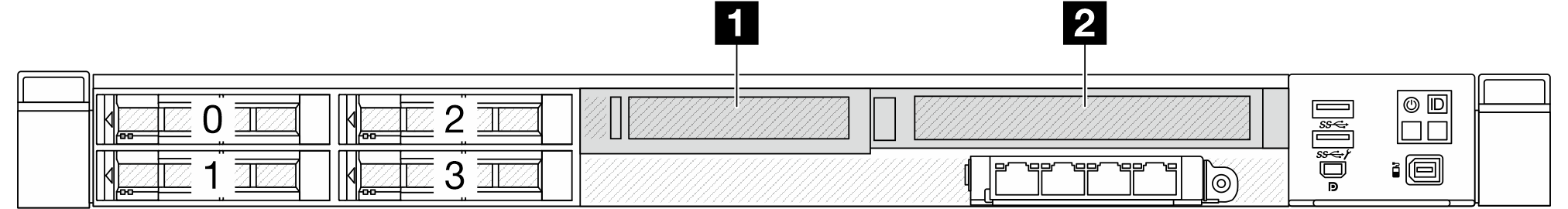
Server front configuration and riser assemblies
See this section to identify the correlations between the front configuration and riser assemblies.
| Server front configuration | Riser 3 assembly | Riser 4 assembly |
|---|---|---|
Figure 1. Two front PCIe slots | Figure 2. LP riser bracket 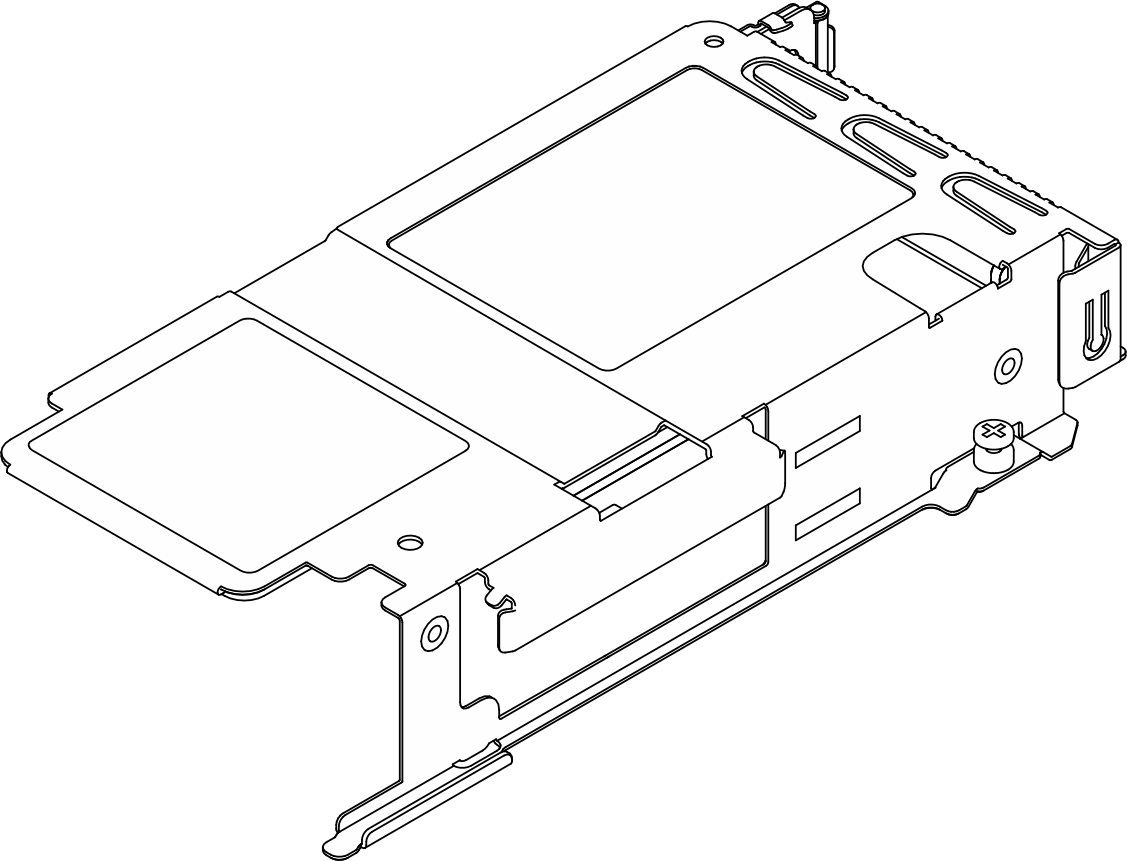 Figure 3. Riser card 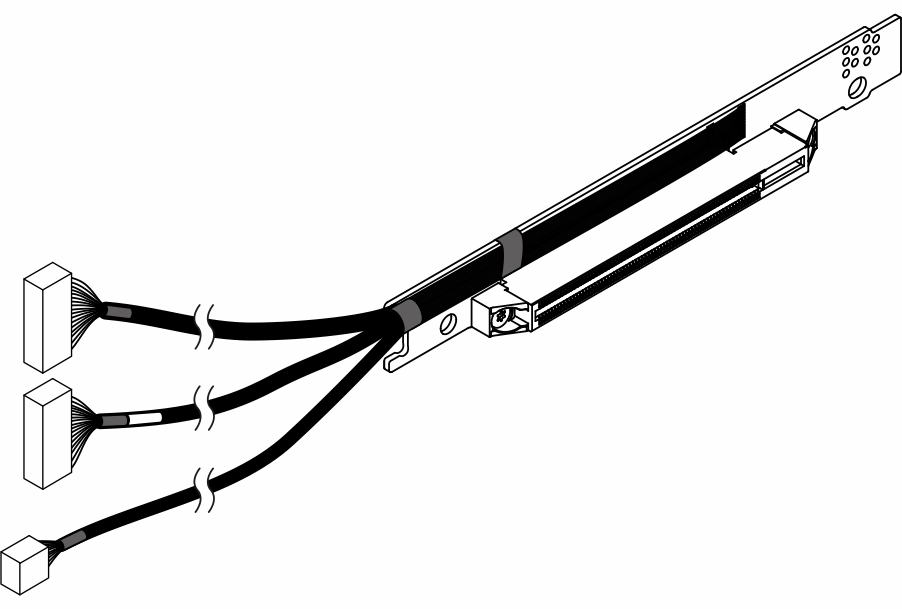 | Figure 4. FH riser bracket 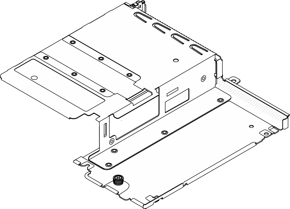 Figure 5. Riser card |
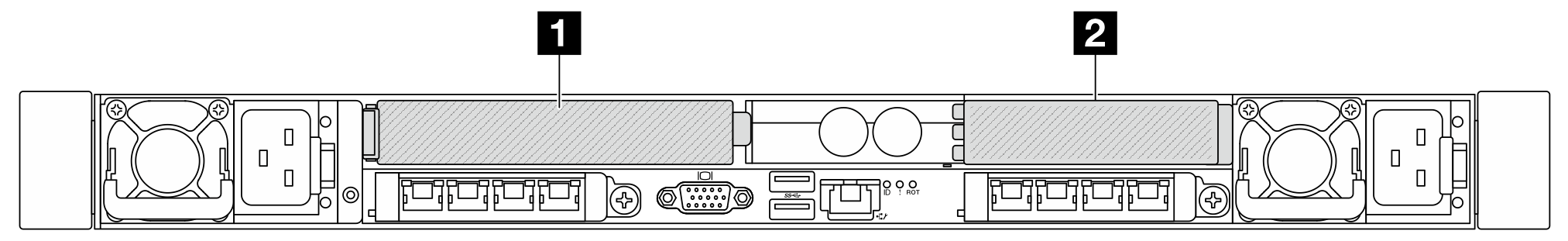
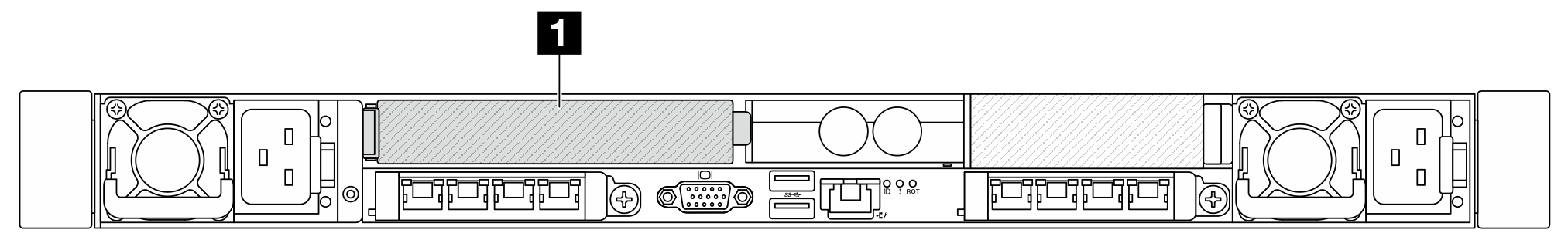
Server rear configuration and riser assemblies
See this section to identify the correlations between the rear configuration and riser assemblies.
| Server rear configuration | Riser 1 assembly | Riser 2 assembly |
|---|---|---|
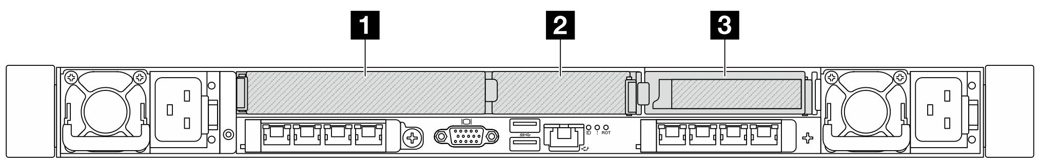
Figure 6. Three PCIe slots | Figure 7. LP-FH riser bracket 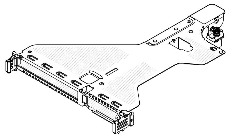 Figure 9. BF riser card 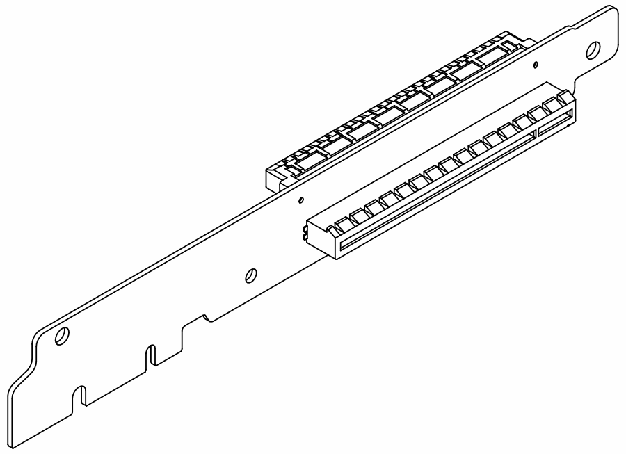 | Figure 10. LP riser bracket 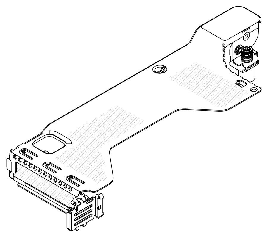 Figure 11. LP riser card 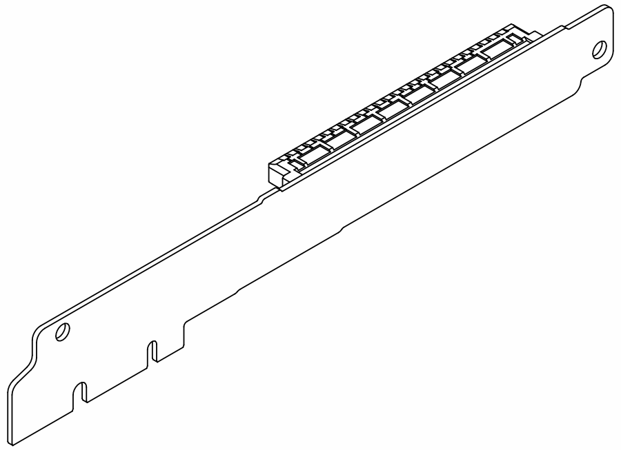 |
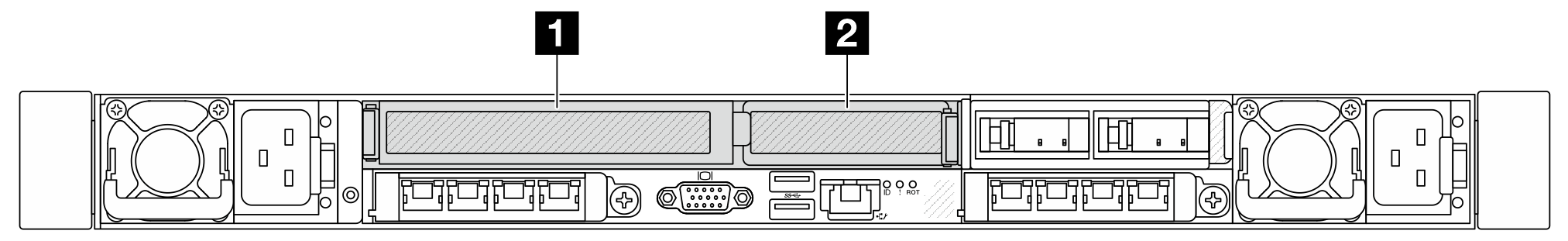
Figure 12. Two PCIe slots | Figure 13. FH riser bracket 1  Figure 14. FH riser card 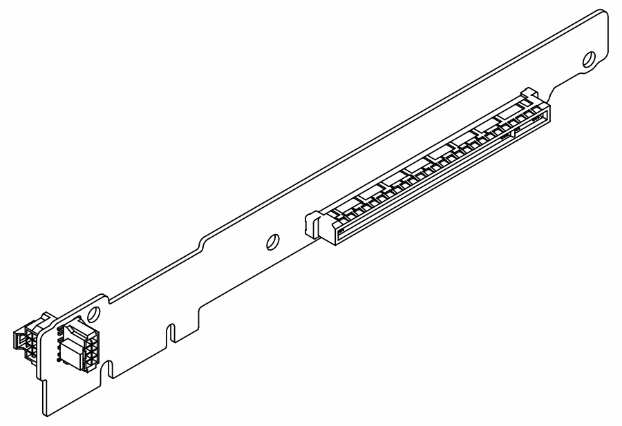 | Figure 15. FH riser bracket 2 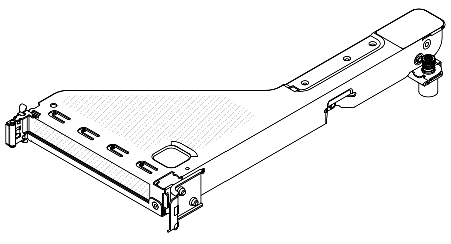 Figure 16. FH riser card |
Figure 17. Two PCIe slots | Figure 18. LP-FH riser bracket Figure 20. BF riser card | Riser 2 assembly is not supported. |
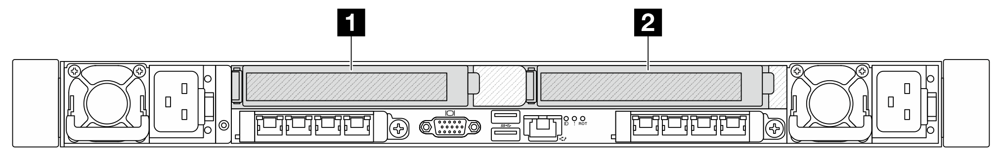
Figure 21. Two PCIe slots | Figure 22. FH riser bracket 3 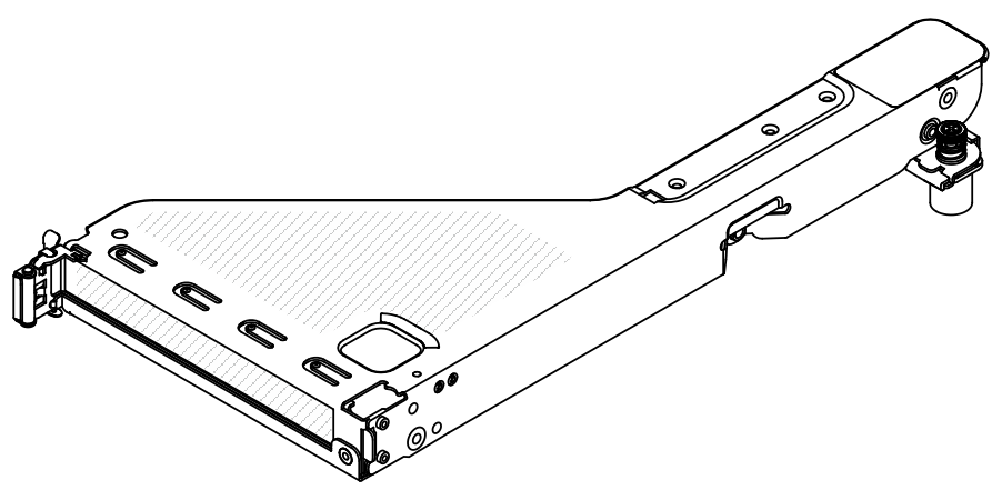 Figure 23. FH riser card | Figure 24. LP riser bracket Figure 25. LP riser card |
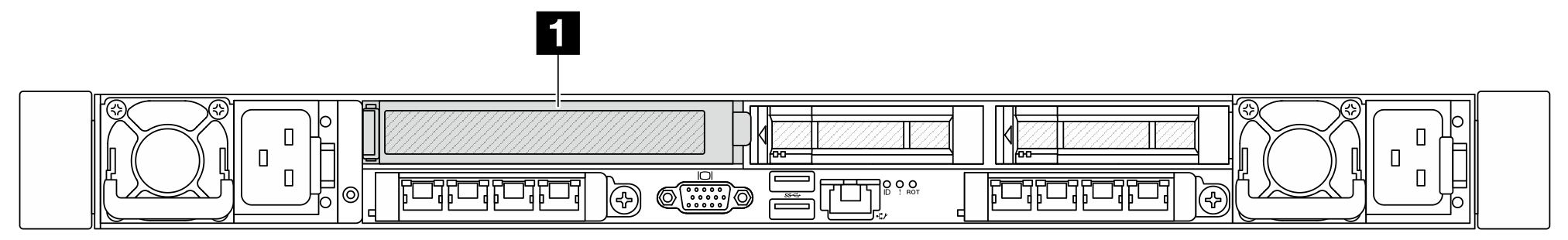
Figure 26. One PCIe slot | Figure 27. FH riser bracket 3 Figure 28. FH riser card | Riser 2 assembly is not supported. |
Figure 29. One PCIe slot | Figure 30. FH riser bracket 3 Figure 31. FH riser card | Riser 2 assembly is not supported. |
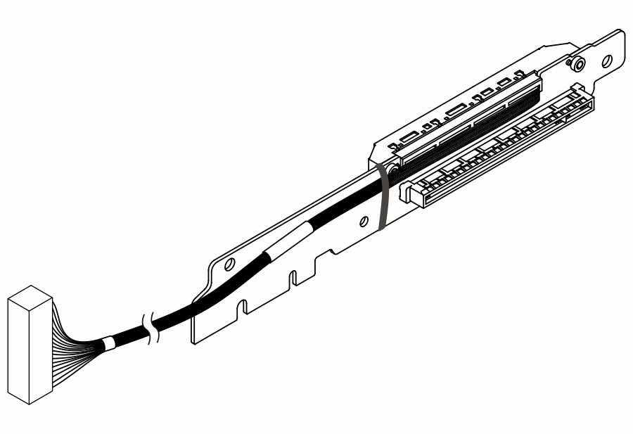
The illustrations of riser brackets and cards may look slightly different from the physical ones.
BF: “butterfly”, a riser card with slots on both sides.