Install the system I/O board or processor board
Follow instructions in this section to install the system I/O board or processor board.
About this task
This task must be operated by trained technicians that are certified by Lenovo Service. Do not attempt to remove or install the part without proper training and qualification.
Read Installation Guidelines and Safety inspection checklist to ensure that you work safely.
Power off the server and peripheral devices and disconnect the power cords and all external cables. See Power off the server.
Prevent exposure to static electricity, which might lead to system halt and loss of data, by keeping static-sensitive components in their static-protective packages until installation, and handling these devices with an electrostatic-discharge wrist strap or other grounding system.
Go to Drivers and Software download website for ThinkSystem SR650 V3 to see the latest firmware and driver updates for your server.
Go to Update the firmware for more information on firmware updating tools.
Procedure
- Depending on your need, do one of the following:
If you are going to replace the system I/O board and reuse the processor board, install a new system I/O board onto the processor board.
If you are going to replace the processor board and reuse the system I/O board, install the existing system I/O board onto a new processor board.
Figure 1. Installing the system I/O board onto the processor board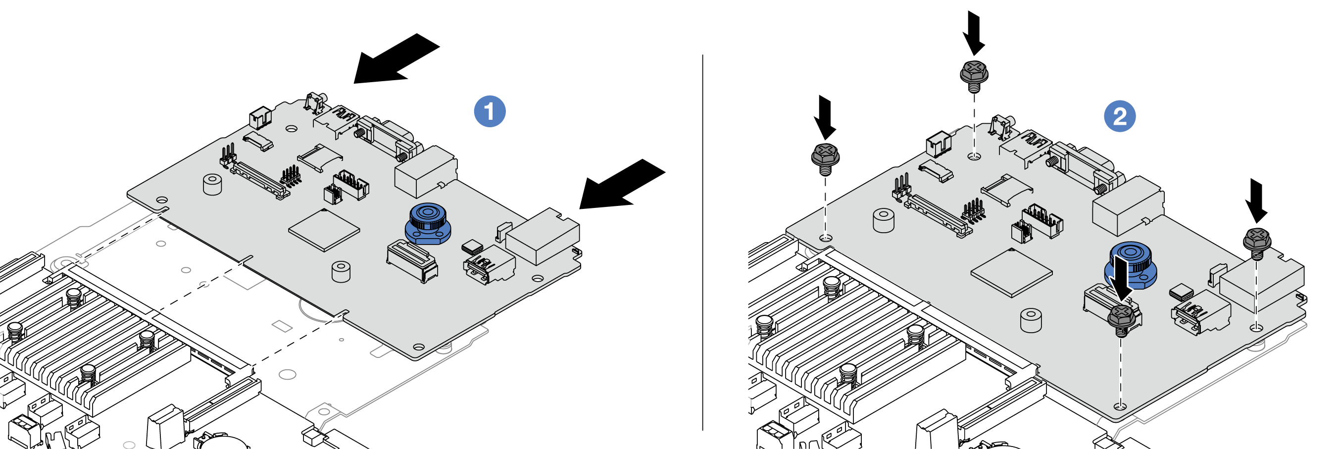
 Align the system I/O board with the connector on the processor board, and use both hands to push the system I/O board and slightly insert it into the connector.NoteTo prevent the contact of the system I/O board from damage, ensure that the system I/O board is aligned correctly with the connector on the processor board, and remains as horizontal as possible during the insertion.
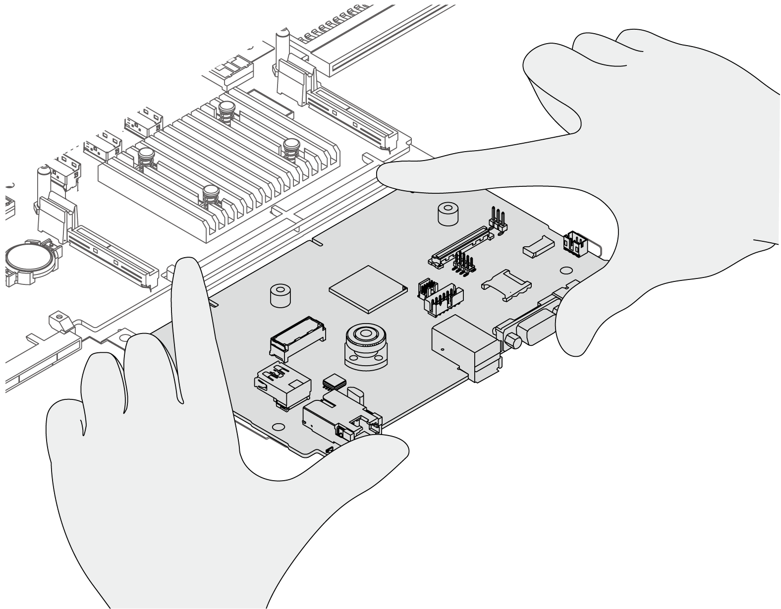
 Install the screws to fix the system I/O board into place.
- Install the system board assembly into the server. Figure 2. System board assembly installation
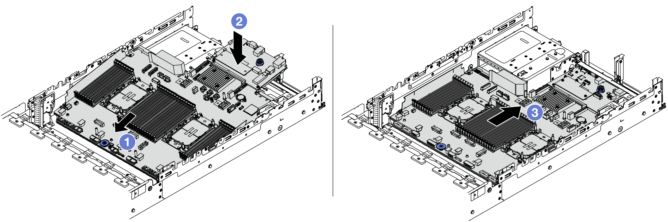
- Insert the front end of the system board assembly towards the front of the chassis until it stops.
- Lower the other end down into the chassis.
 Slide the system board assembly towards the rear of the chassis until it clicks into place. Ensure that rear connectors on the system I/O board are inserted into the corresponding holes in the rear panel.
After you finish
- Install any components that you have removed:
Reconnect all the required cables to the same connectors on the system board assembly. See Internal cable routing.
Ensure that all components have been reassembled correctly and that no tools or loose screws are left inside the server.
Reinstall the top cover. See Install the top cover.
If the sever was installed in a rack, reinstall the server into the rack. See Install the server to rack.
Reconnect the power cords and any cables that you removed.
Power on the server and any peripheral devices. See Power on the server.
Update the vital product data (VPD). See Update the Vital Product Data (VPD).
Machine type number and serial number can be found on the ID label, see Identify the server and access the Lenovo XClarity Controller.
Optionally, enable UEFI Secure Boot. See Enable UEFI Secure Boot.
Demo video