Install a front high watts GPU riser assembly
Follow the instructions in this section to install a front high watts GPU riser assembly.
About this task
Read Installation Guidelines and Safety inspection checklist to ensure that you work safely.
Power off the server and peripheral devices and disconnect the power cords and all external cables. See Power off the server.
Prevent exposure to static electricity, which might lead to system halt and loss of data, by keeping static-sensitive components in their static-protective packages until installation, and handling these devices with an electrostatic-discharge wrist strap or other grounding system.
Procedure
- Install the riser assembly into chassis. Figure 1. Front high watts GPU riser assembly installation
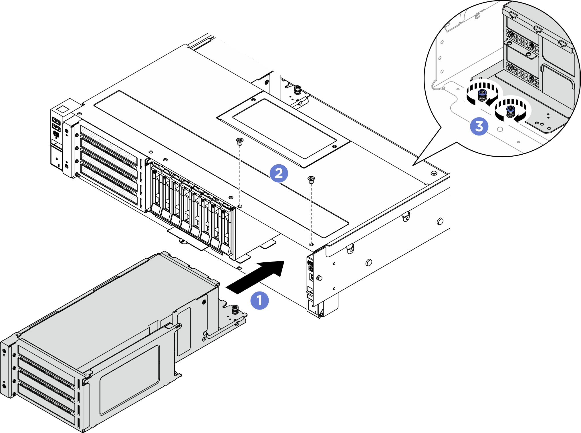
 Carefully slide the riser assembly into the chassis until the riser assembly is seated in place.
 Fasten two screws to secure the riser assembly.
 Fasten the two thumbscrews at the rear of riser assembly.
- For PCIe riser assembly 7, connect cables to the system board assembly. Make sure to complete the following procedure to route the cables.NoteSR650a V4 supports up to two high watts GPUs (up to 600W) installed in Slot 21 and Slot 23 of PCIe riser assembly 7.
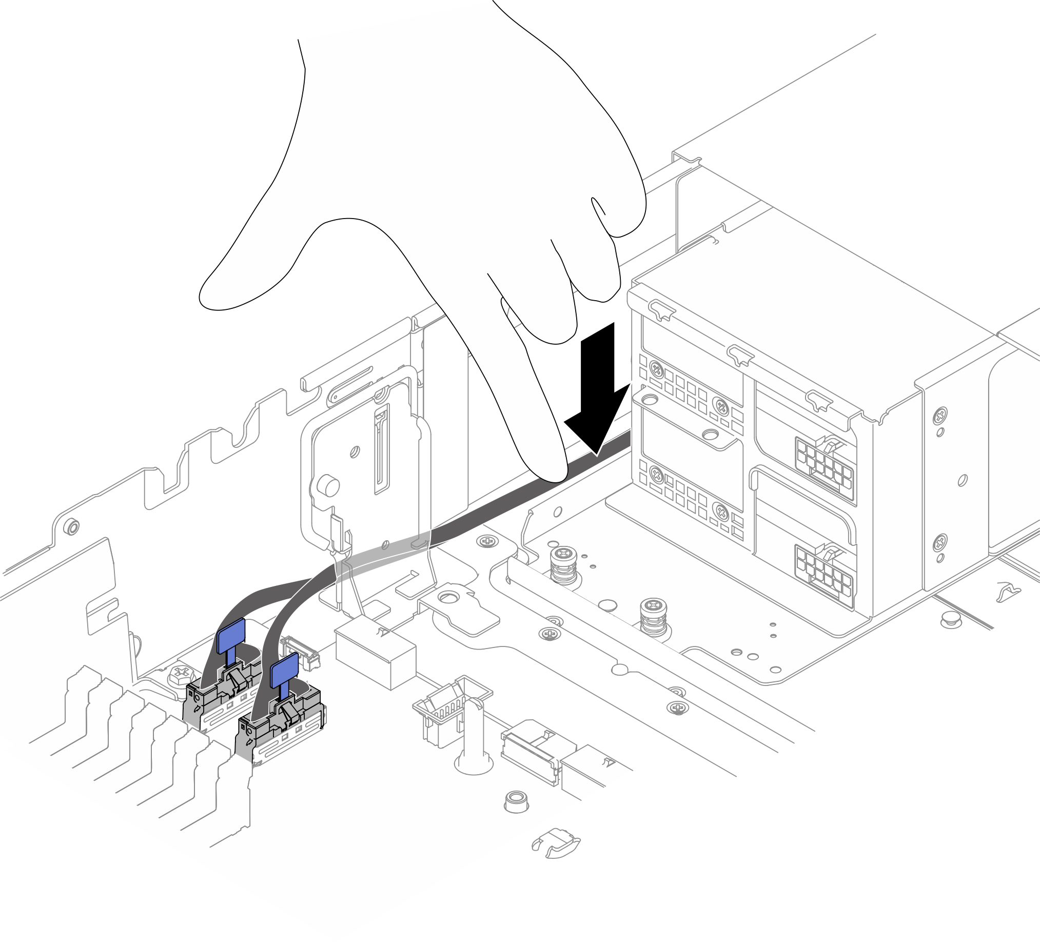
In configuration with high watts GPUs, PCIe riser assembly 6 (Slot 16, 17, 18, 19) comes without riser cards. - Connect the signal cable of Slot 23 riser card (the lower riser card in the riser cage) to PCIe connector 1 and PCIe connector 2 on the system board. Then, route the cable between the bracket and the chassis wall as shown in the illustration. Press the cable down to the bottom of chassis.NoteIf necessary, bend the cable to make sure it is fully secured in the space between the bracket and the chassis wall.Figure 2. Slot 23 riser card signal cable routing
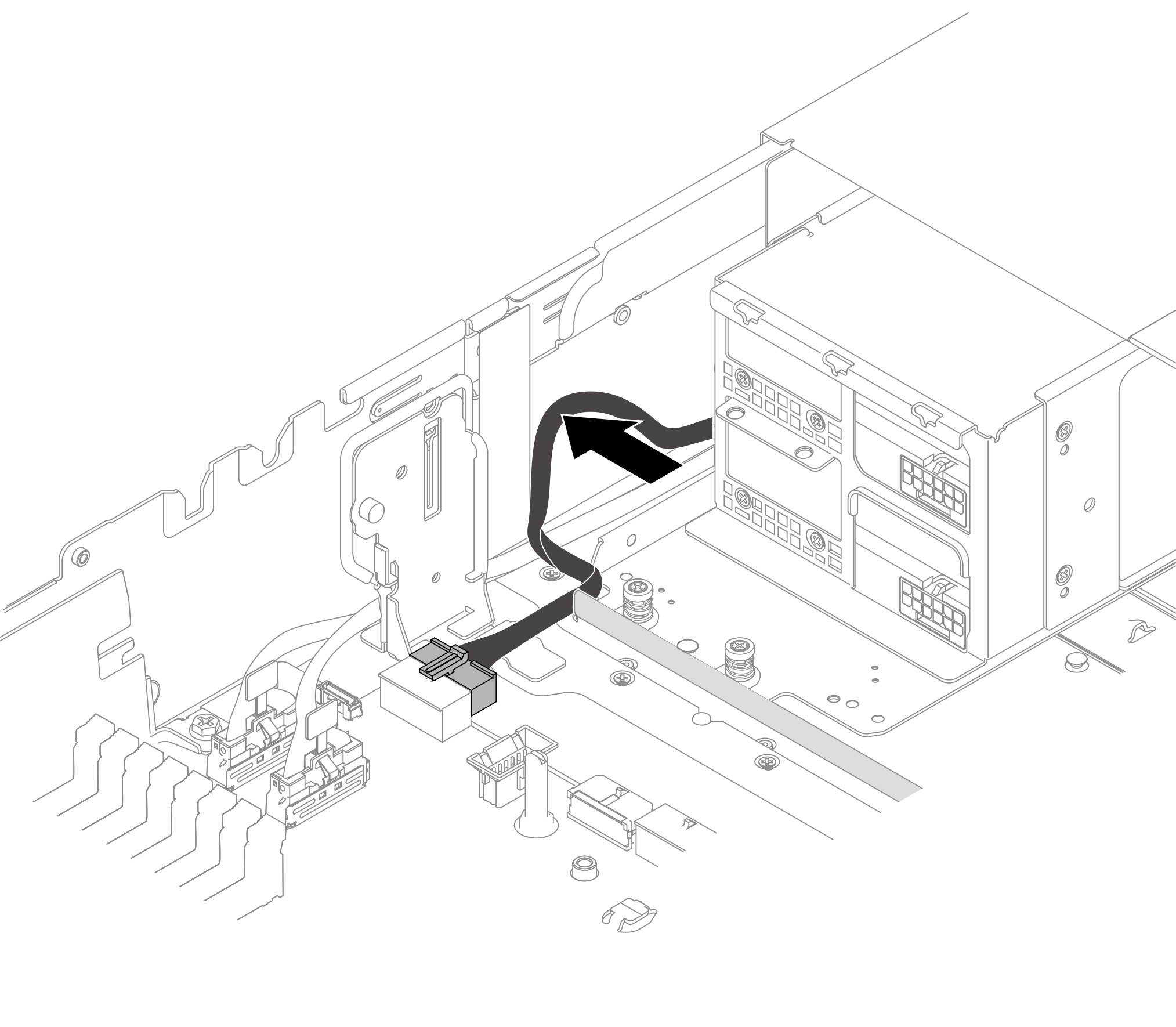
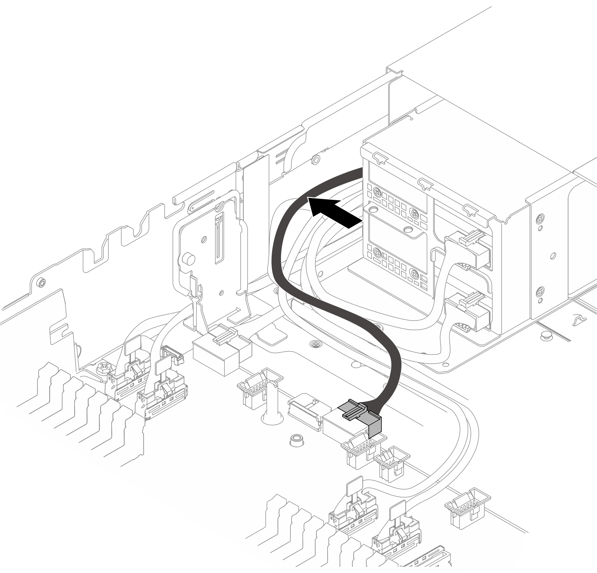
- Connect the power cable of Slot 23 riser card to Power connector 4 on the system board. Route the cable as shown in the illustration, and press the cable toward chassis wall.Figure 3. Slot 23 riser card power cable routing
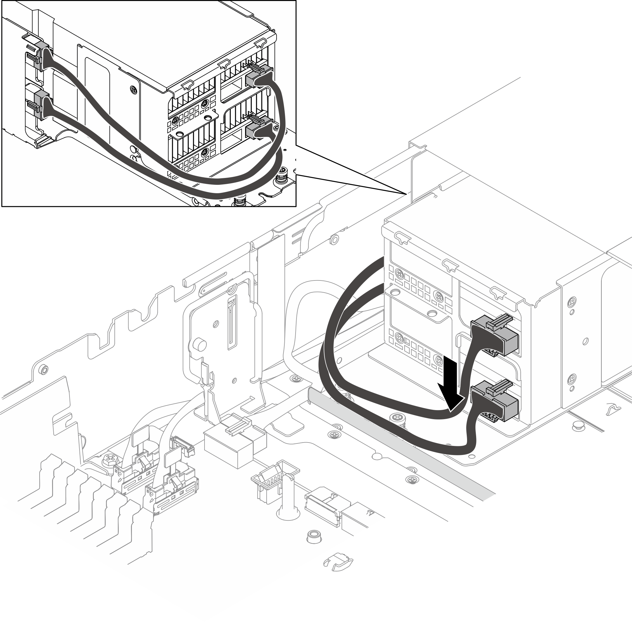
- Bend the GPU power cable from the upper GPU adapter downwards. Then, route the two GPU power cables along the wall at chassis bottom as shown in the illustration.NoteWhen routing the GPU power cables along the wall, do not let the cables cover each other.Figure 4. GPU power cable routing
- Connect the signal cable of Slot 21 riser card (the upper riser card in the riser cage) to the corresponding PCIe connectors on the system board. Then, route the cable along the wall at chassis bottom as shown in the illustration.
Table 1. PCIe connectors for Slot 21 riser card GPU adapter Processor configuration PCIe connectors for Slot 21 riser card ThinkSystem NVIDIA H200 NVL 141GB PCIe GPU Gen5 Passive GPU 1P PCIe connector 3, PCIe connector 4 2P ThinkSystem NVIDIA RTX PRO 6000 Blackwell Server Edition 96GB PCIe Gen5 Passive GPU 1P PCIe connector 3, PCIe connector 4 2P PCIe connector 5, PCIe connector 6 NoteThe connectors shown in following illustration are for reference. Make sure to connect Slot 21 riser card to the connectors corresponding to the selected configuration.Figure 5. Slot 21 riser card signal cable routing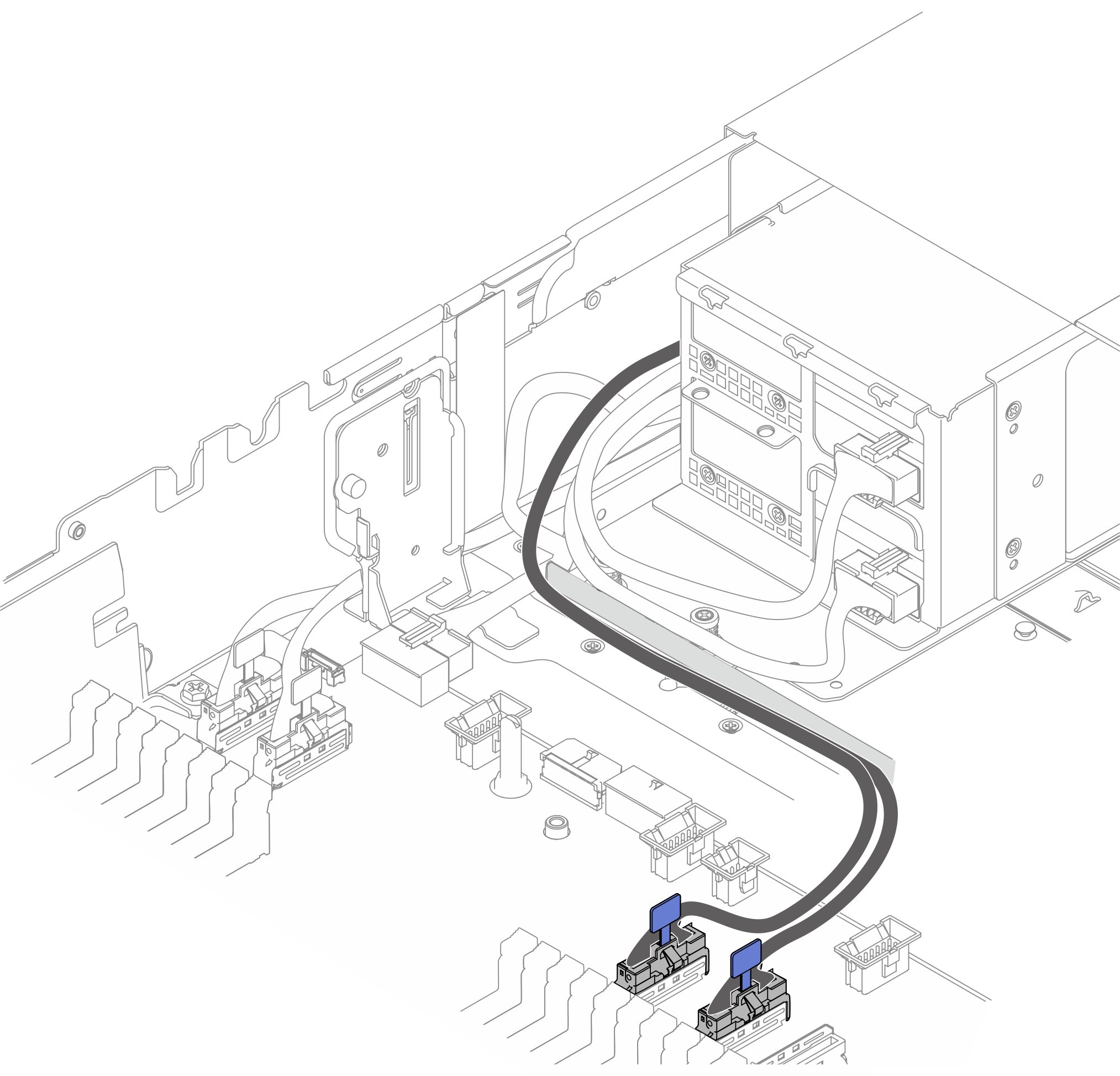
- Connect the power cable of Slot 21 riser card to Power connector 3 on the system board. Then, press the cable toward the chassis wall as shown in the illustration.Figure 6. Slot 21 riser card power cable routing
- Connect the signal cable of Slot 23 riser card (the lower riser card in the riser cage) to PCIe connector 1 and PCIe connector 2 on the system board. Then, route the cable between the bracket and the chassis wall as shown in the illustration. Press the cable down to the bottom of chassis.
After you finish
Install the front high watts GPU air duct. See Install the front high watts GPU air duct.
Complete the parts replacement. See Complete the parts replacement
Demo video