Install a GPU and heat sink module
Follow instructions in this section to install a GPU and heat sink module. The procedure must be executed by a trained technician.
About this task
Attention
- Read Installation Guidelines and Safety inspection checklist to ensure that you work safely.
- Touch the static-protective package that contains the component to any unpainted metal surface on the server; then, remove it from the package and place it on a static-protective surface.
- Two people and one lifting device on site that can support up to 400 lb (181 kg) are required to perform this procedure. If you do not already have a lifting device available, Lenovo offers the Genie Lift GL-8 material lift that can be purchased at Data Center Solution Configurator. Make sure to include the Foot-release brake and the Load Platform when ordering the Genie Lift GL-8 material lift.
- Make sure to inspect the connectors and sockets on the GPU and the GPU baseboard. Do not use the GPU or the GPU baseboard if its connectors are damaged or missing, or if there are debris in the sockets. Replace the GPU or the GPU baseboard with a new one before continuing the installation procedure.
- GPU and heat sink is one part. Do not remove the heat sink from the GPU.
- The following table shows the mapping information about the physical GPU sockets, slot numbering in XCC, and module IDs in nvidia-smi.
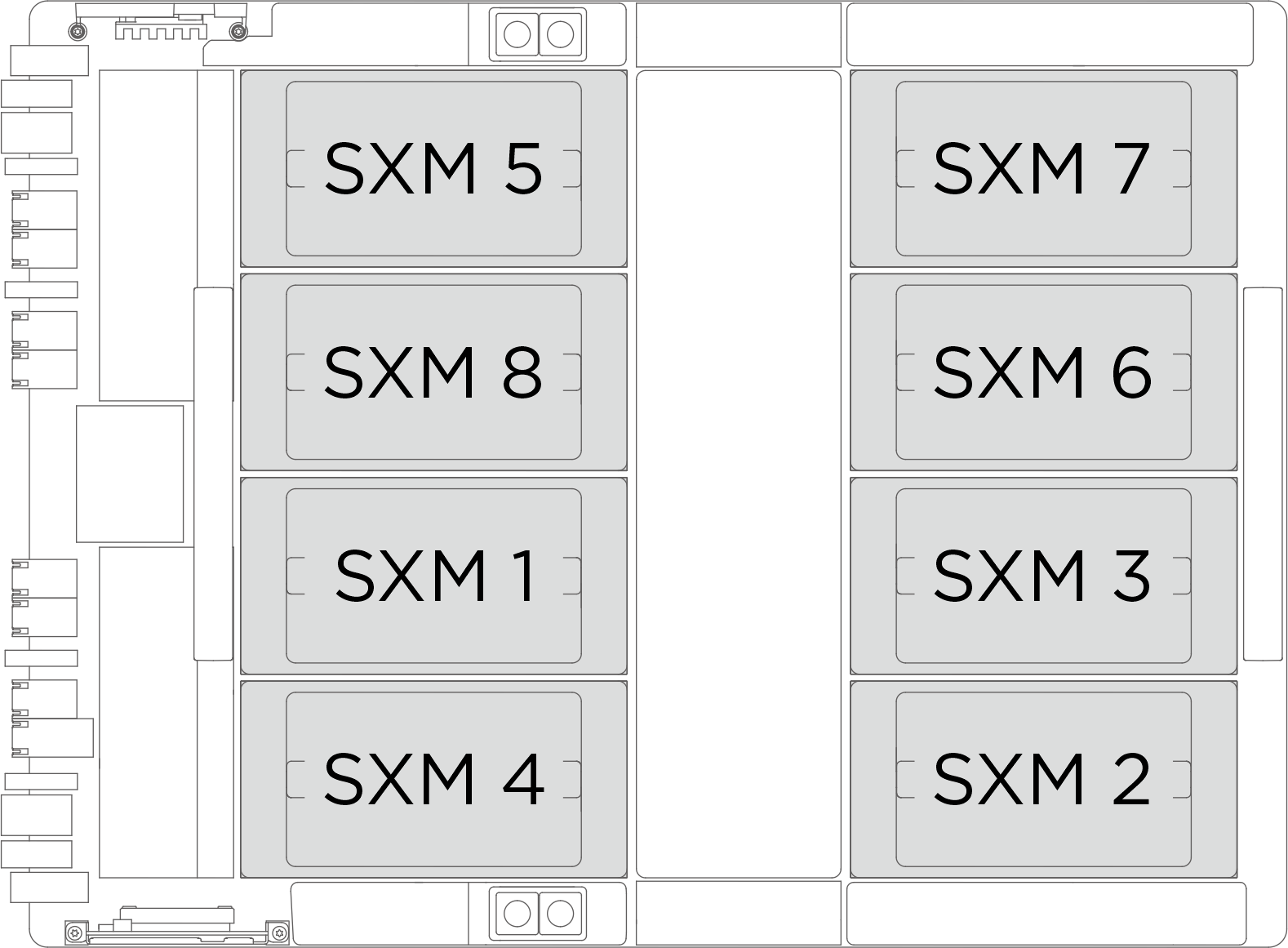
Physical GPU socket Slot numbering in XCC Module ID in nvidia-smi SXM 1 Slot 21 1 SXM 2 Slot 24 2 SXM 3 Slot 22 3 SXM 4 Slot 23 4 SXM 5 Slot 17 5 SXM 6 Slot 20 6 SXM 7 Slot 18 7 SXM 8 Slot 19 8
Note
Make sure you have the required tools listed below available to properly replace the component:
- Torque screwdrivers
- Two Torx T15 extended bits (300 mm long)
- One B200 jig
Firmware and driver download: You might need to update the firmware or driver after replacing a component.
Go to Drivers and Software download website for ThinkSystem SR680a V3 to see the latest firmware and driver updates for your server.
Go to Update the firmware for more information on firmware updating tools.
Procedure
- (Optional) Complete the following steps for the new GPU and heat sink module.
- Remove the connector covers at the bottom.
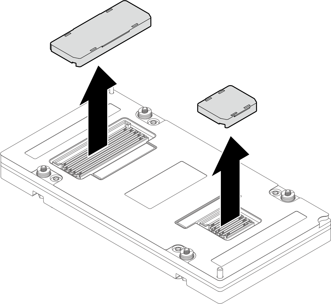
- Remove the protective film from the heat sink.
- Remove the plastic cover from the heat sink.
- Remove the connector covers at the bottom.
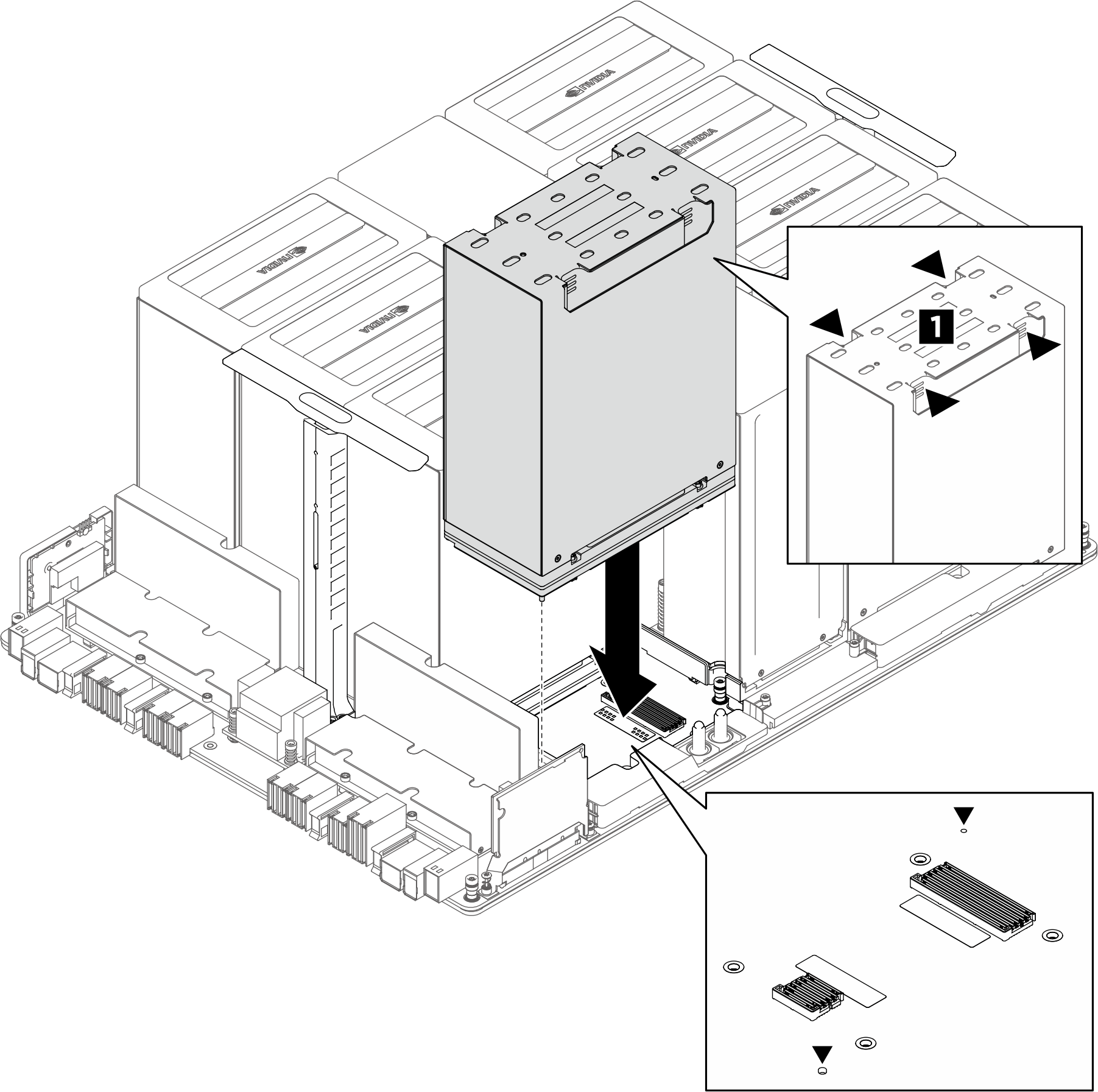
- Use both hands to grasp the recessed area of the GPU and heat sink module (1); then, align the module with the two guide holes on the GPU baseboard and gently place it onto the GPU baseboard.Figure 1. GPU and heat sink module installation
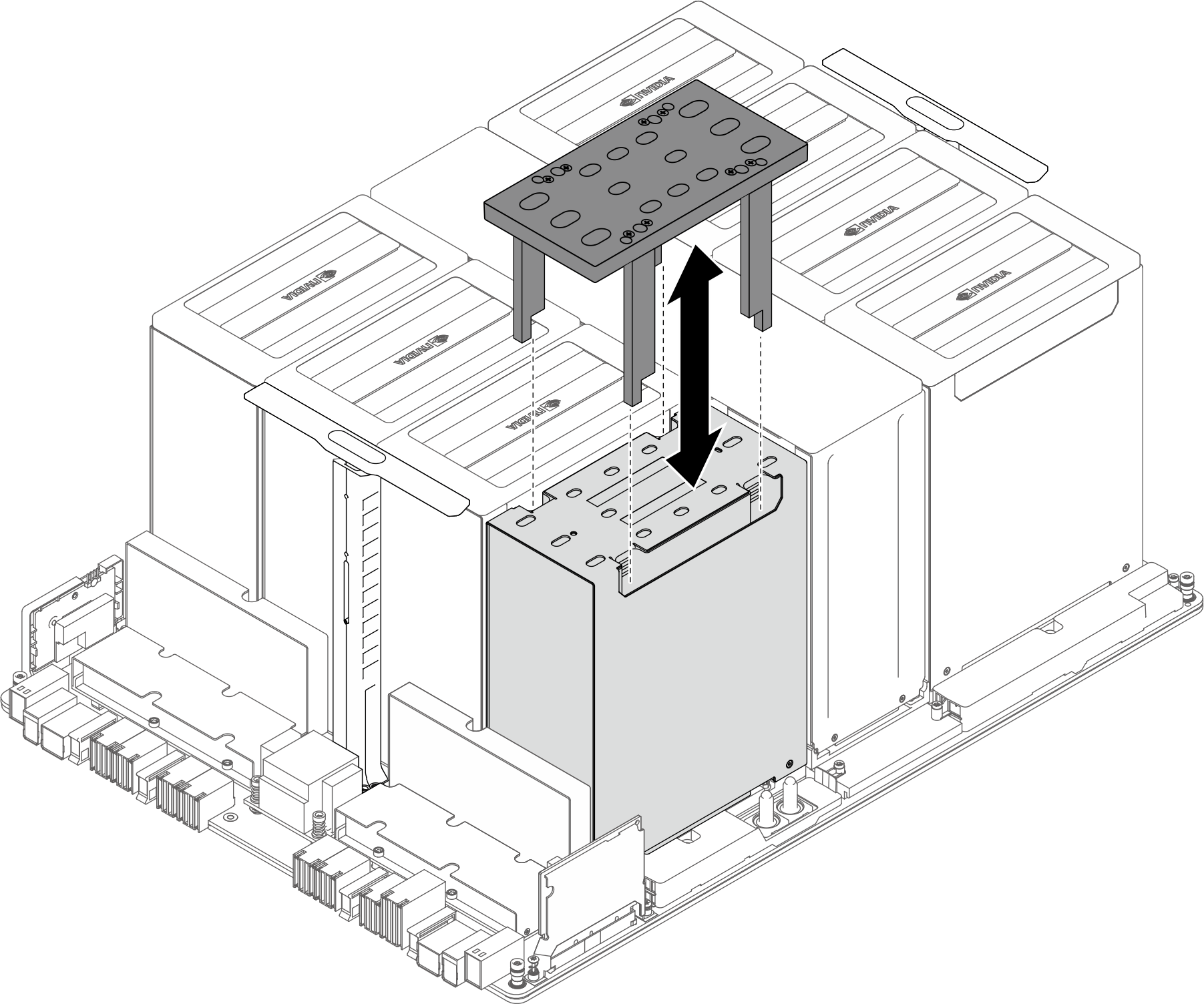
- Align the jig with the GPU heat sink and carefully install it onto the GPU heat sink.Figure 2. Jig installation
- Install the four Torx T15 screws to secure the GPU and heat sink module.
- First torque setting:
- Set the torque screwdrivers to 0.11±0.011 newton-meters, 0.97±0.097 inch-pounds.
- Insert the two screwdrivers into the designated holes on the jig to simultaneously fasten the two diagonal screws (
 ) for a few rounds.
 - Insert the two screwdrivers into the designated holes on the jig to simultaneously fasten the two diagonal screws (
 ) for a few rounds.
- Second torque setting:
- Set the torque screwdrivers to 0.78±0.031 newton-meters, 6.90±0.274 inch-pounds.
- Insert the two screwdrivers into the designated holes on the jig to simultaneously fasten the two diagonal screws () for a few rounds.
- Insert the two screwdrivers into the designated holes on the jig to simultaneously fasten the two diagonal screws () for a few rounds.
- Final torque setting:
- Set the torque screwdrivers to 0.81±0.032 newton-meters, 7.17±0.283 inch-pounds.
- Insert the two screwdrivers into the designated holes on the jig and fully tighten the two diagonal screws () simultaneously.
- Insert the two screwdrivers into the designated holes on the jig and fully tighten the two diagonal screws () simultaneously.
NoteTwo people are required to fasten the screws simultaneously.Figure 3. Screw installation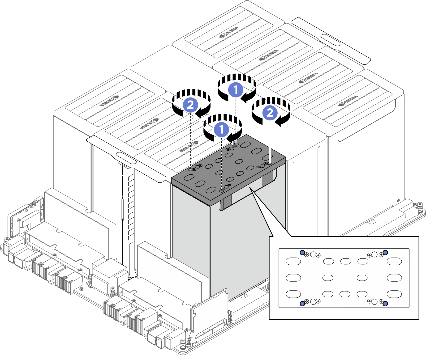
- First torque setting:
- Remove the jig from the GPU heat sink.Figure 4. Jig removal
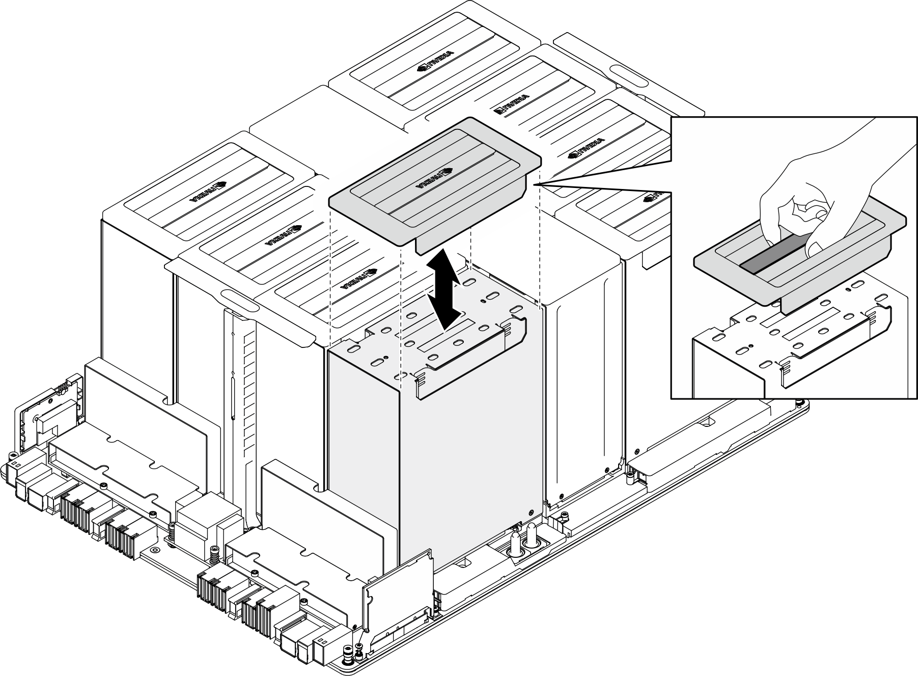
- Place the plastic cover onto the GPU and heat sink module until it is securely seated.Figure 5. Plastic cover installation
After you finish
- (GPU and heat sink module 2, 4, 5, and 7 only) Reinstall the GPU air duct. See Install a GPU air duct.
- Reinstall the power complex. See Install the power complex.
- Reinstall the cable holder frame and baffle assembly. See Install the cable holder frame and baffle assembly.
- Reinstall the compute tray. See Install the compute tray.
- Reinstall the system shuttle. See Install the system shuttle.
- Complete the parts replacement. See Complete the parts replacement.
Give documentation feedback