Install the integrated diagnostics panel
Follow instructions in this section to install the integrated diagnostics panel. The procedure must be executed by a trained technician.
About this task
Attention
- Read Installation Guidelines and Safety inspection checklist to ensure that you work safely.
- Touch the static-protective package that contains the component to any unpainted metal surface on the server; then, remove it from the package and place it on a static-protective surface.
Procedure
 Align the integrated diagnostics panel with the slot in the front of the chassis, and slide it in.
 Connect the cable to the integrated diagnostics panel.Figure 1. Integrated diagnostics panel installation
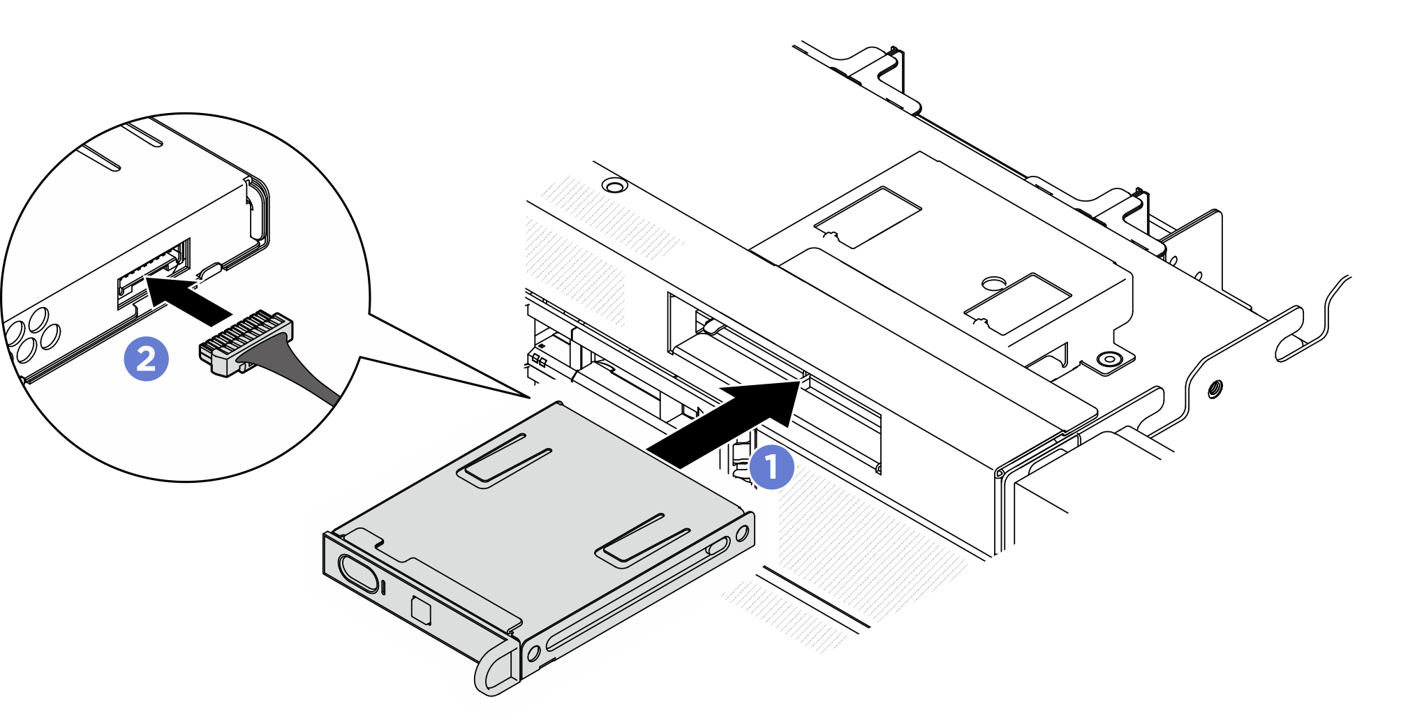
- If necessary, attach the labels to both ends of the cable.
- Attach the white space portion of the label to one end of the cable.
- Wrap the label around the cable and attach it to the white space portion.
- Repeat to attach the other label to the opposite end of the cable.
Figure 2. Label application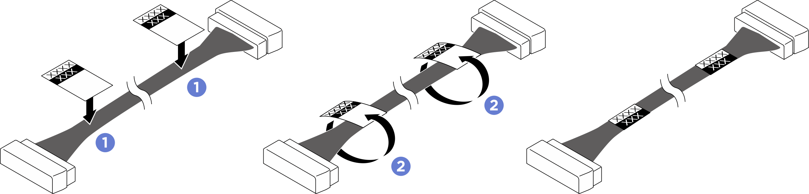 NoteSee the table below to identify the corresponding labels for the cable.
From To Label Integrated diagnostics panel: Integrated diagnostics panel cable System board assembly: Integrated diagnostics panel connector (FRONT IO2) - Pong
- FRONT IO2
After you finish
- Reinstall the I/O cover. See Install the I/O cover.
- Reinstall the front top cover. See Install the front top cover.
- Complete the parts replacement. See Complete the parts replacement.
Give documentation feedback