Remove a front B200 GPU
Follow instructions in this section to remove a front B200 GPU. The procedure must be executed by a trained technician.
About this task
Attention
- Read Installation Guidelines and Safety inspection checklist to ensure that you work safely.
- Power off the server and peripheral devices and disconnect the power cords and all external cables. See Power off the server.
- If the server is installed in a rack, slide the server out on its rack slide rails to gain access to the top cover, or remove the chassis from the rack. See Remove the server from rack.
- Two people and one lifting device on site that can support up to 400 lb (181 kg) are required to perform this procedure. If you do not already have a lifting device available, Lenovo offers the Genie Lift GL-8 material lift that can be purchased at Data Center Solution Configurator. Make sure to include the Foot-release brake and the Load Platform when ordering the Genie Lift GL-8 material lift.
- A torque screwdriver is available for request if you do not have one at hand.
Note
Make sure you have the required tools listed below available to properly replace the component:
- Torx T15 head screwdriver
- 2 x Torx T15 200mm extension bit
- Phillips #1 head screwdriver
- Phillips #2 head screwdriver
- Alcohol cleaning pad
- B200 PCM
- B200 SXM6 PAD-1
- B200 SXM6 PAD-2
- B200 GPU service kit
Important
Putty pad/phase change material (PCM) replacement guidelines
- Before replacing the putty pad/PCM, gently clean the hardware surface with an alcohol cleaning pad.
- Hold the putty pad/PCM carefully to avoid deformation. Make sure no screw hole or opening is blocked by the putty pad/PCM.
- Do not use expired putty pad/PCM. Check the expiry date on putty pad/PCM package. If the putty pads/PCM are expired, acquire new ones to properly replace them.
The following illustration shows the B200 GPU numbering and corresponding slot numbering in XCC.
Figure 1. B200 GPU numbering
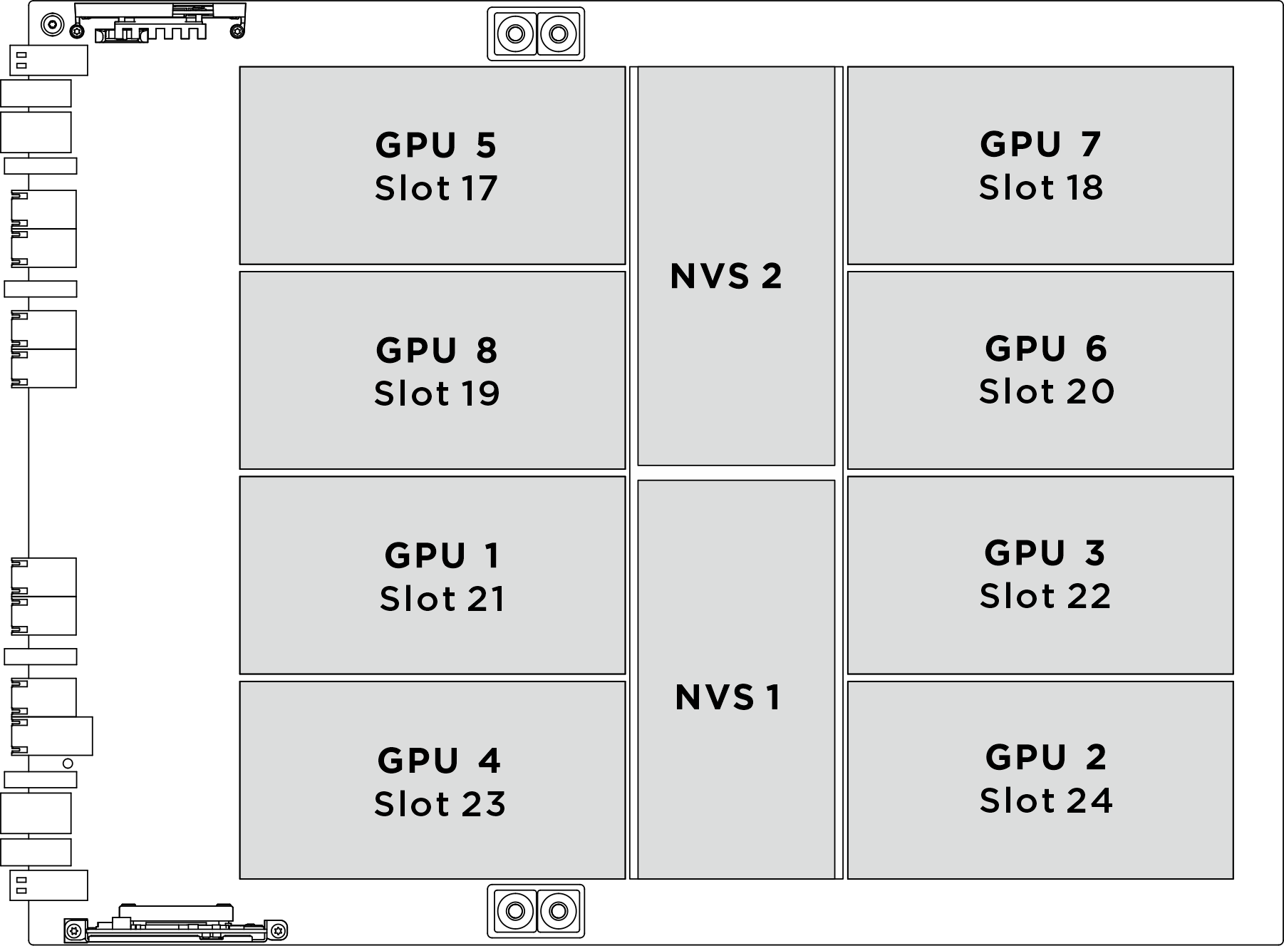
| Physical GPU socket | Slot numbering in XCC | Module ID in nvidia-smi |
|---|---|---|
SXM 1 | Slot 21 | 1 |
SXM 2 | Slot 24 | 2 |
SXM 3 | Slot 22 | 3 |
SXM 4 | Slot 23 | 4 |
SXM 5 | Slot 17 | 5 |
SXM 6 | Slot 20 | 6 |
SXM 7 | Slot 18 | 7 |
SXM 8 | Slot 19 | 8 |
Procedure
- Reposition the rear B200 GPU cold plate manifold to create space for front B200 GPU. Install the two service brackets onto the rear GPU cold plates.
 Align the guide pins on the service bracket with the guide holes on the GPU cold plate; then, lower it onto the cold plate.
 Fasten the two captive screws (PH1, 2 x M3, 0.5 newton-meters, 4.3 inch-pound) to install the service bracket onto the rear GPU cold plate. Repeat to install another service bracket.Figure 2. Installing the service brackets to the rear GPU cold plates
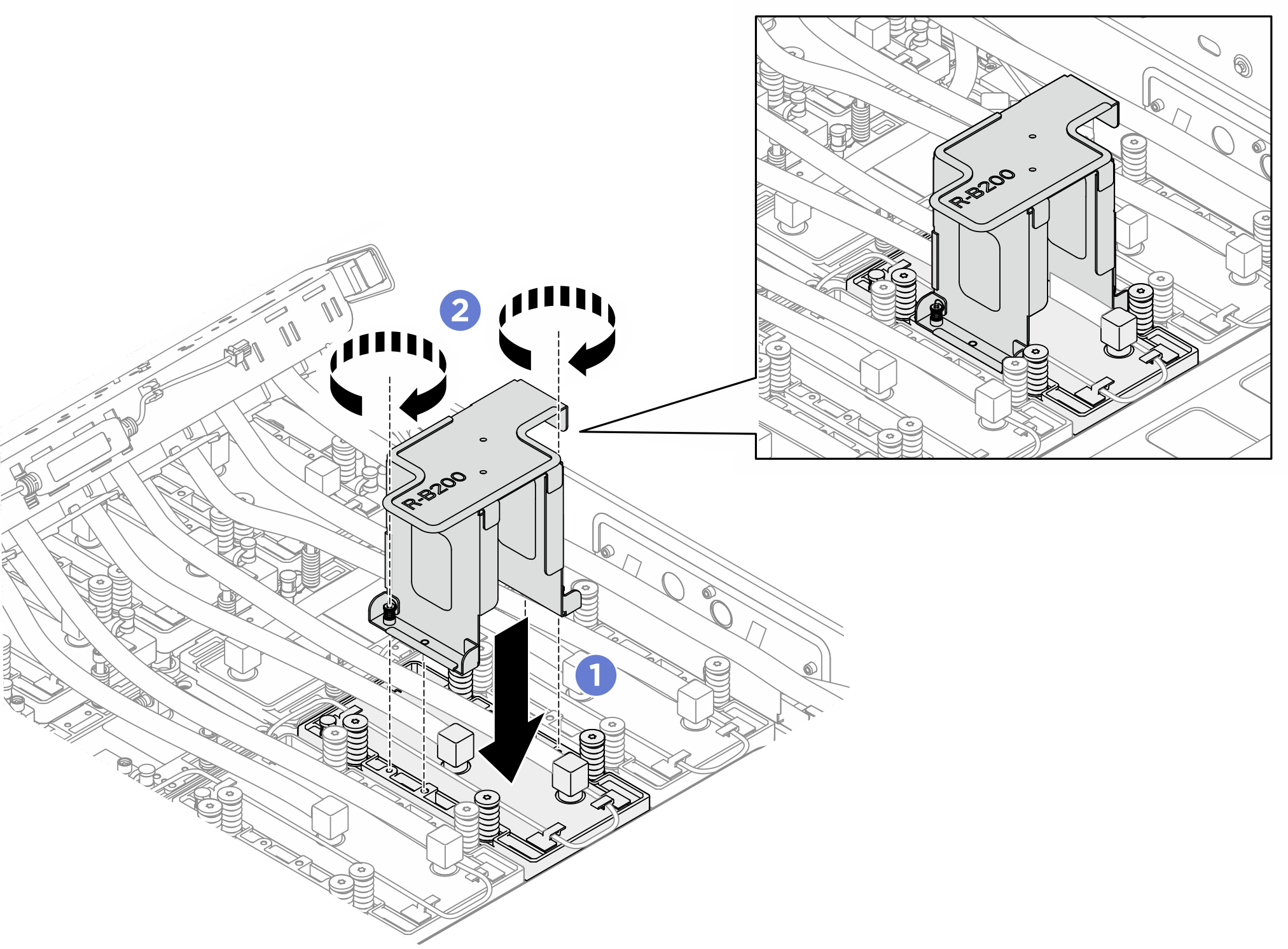 NoteAvoid pinching the leakage sensor module cable when installing the bracket.
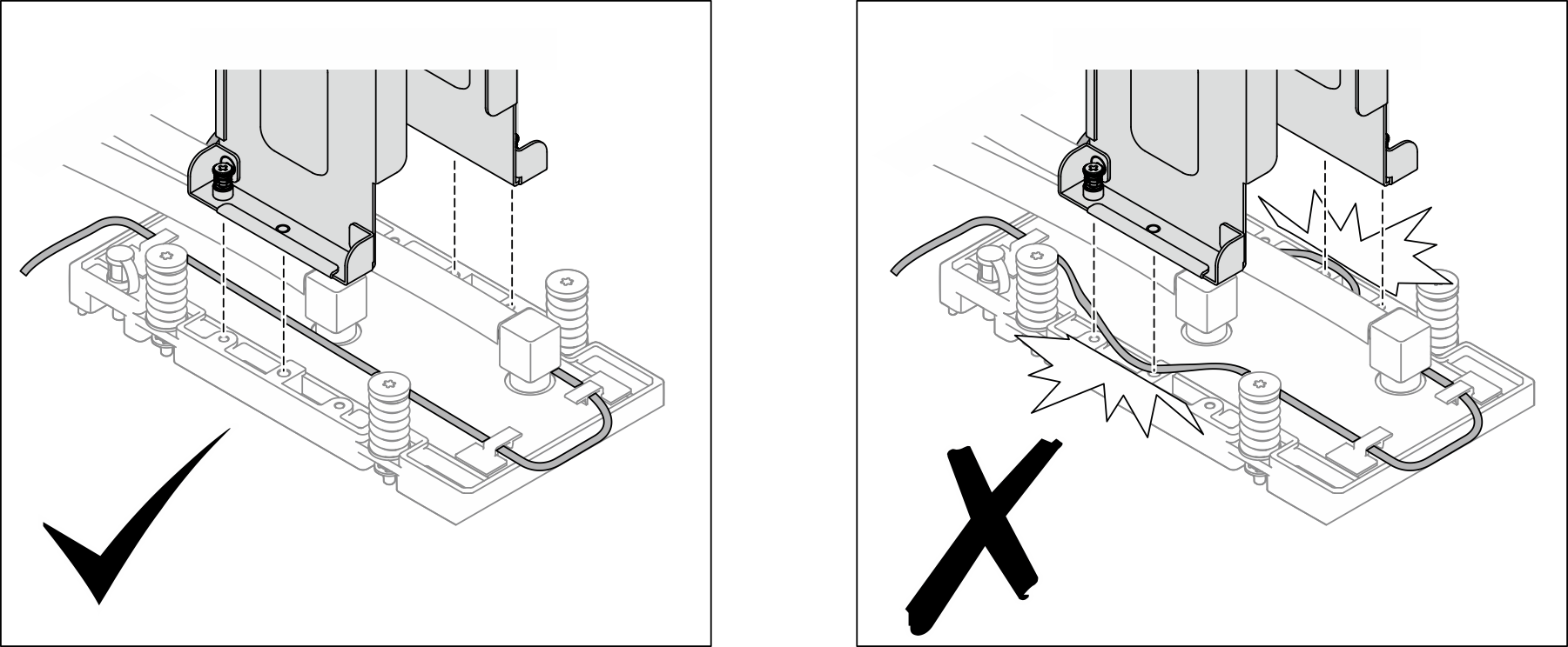
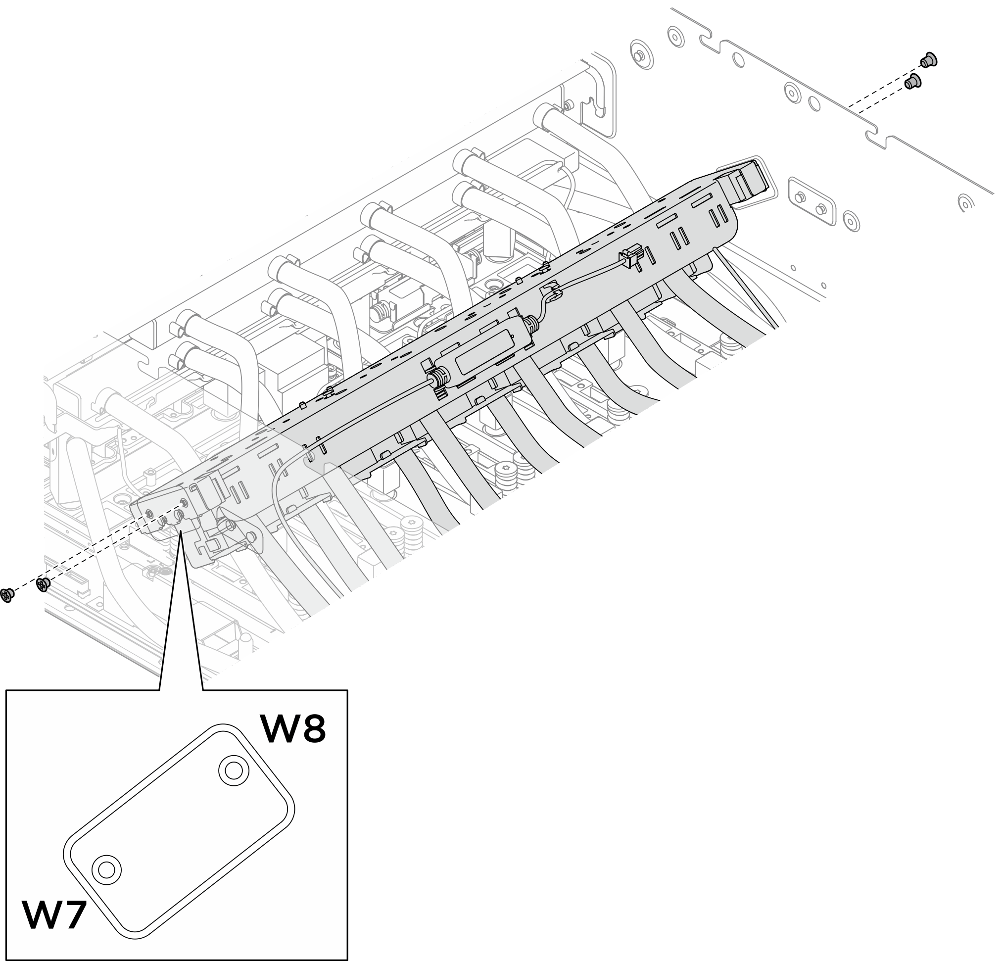
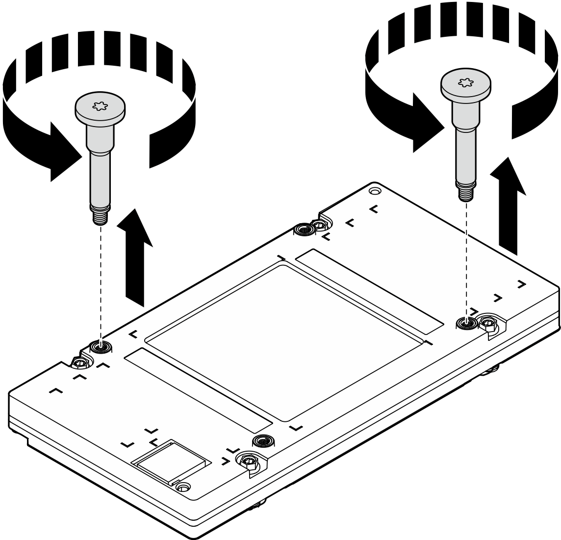
- Unfasten the four M3 screws (W7-W8) that secure the rear B200 GPU cold plate module manifold to the chassis.Figure 3. Removing the rear B200 GPU cold plate module manifold
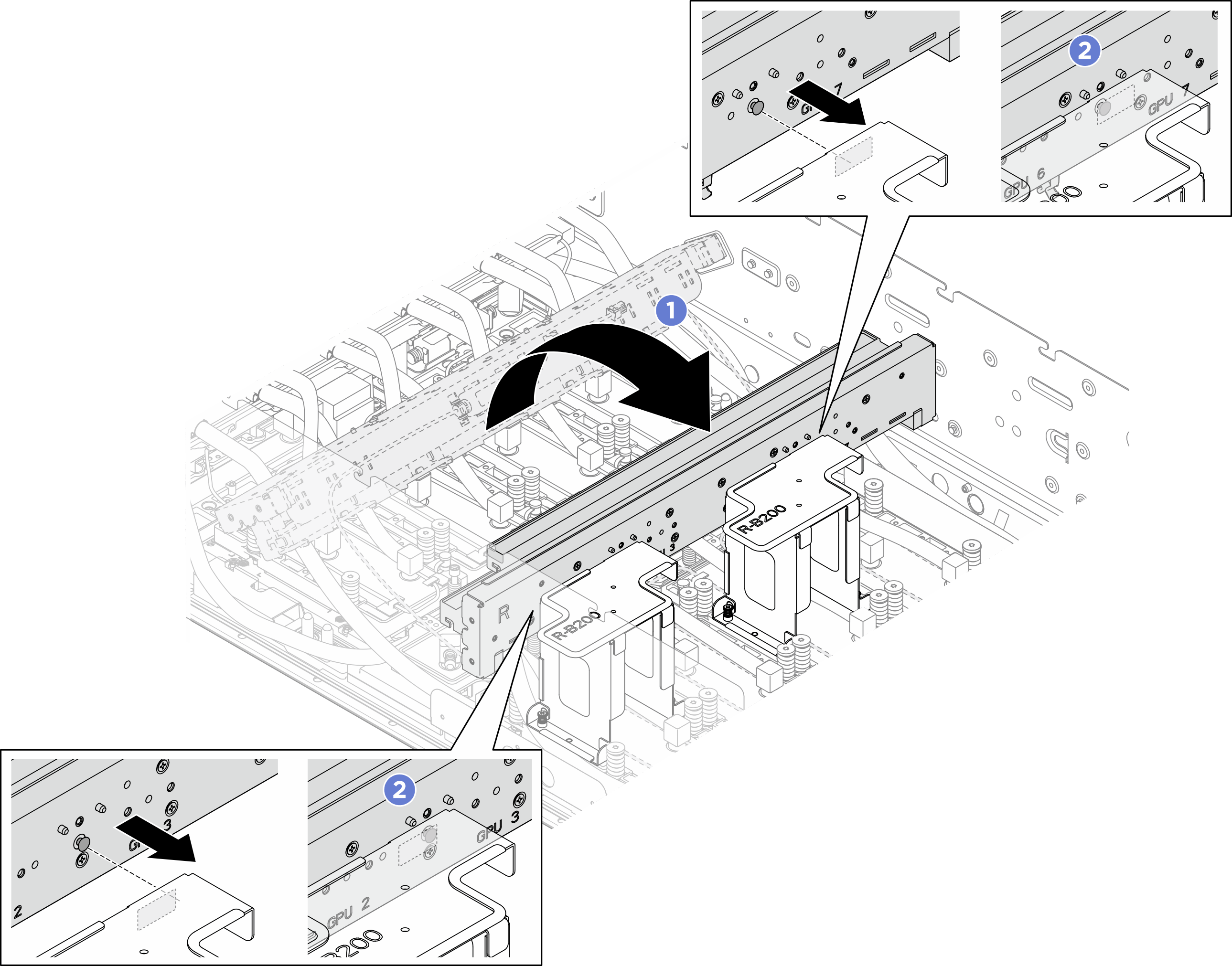
- Reposition the rear B200 GPU cold plate module manifold.
- Flip over the rear B200 GPU cold plate module manifold as illustrated. Align and insert the guide pins on the manifold into the guide slots on the shipping brackets; then, engage the manifold to the service brackets.
- Ensure the guide pins on the manifold are securely engaged with the guide slots on the shipping brackets.Figure 4. Repositioning the rear GPU cold plate module manifold
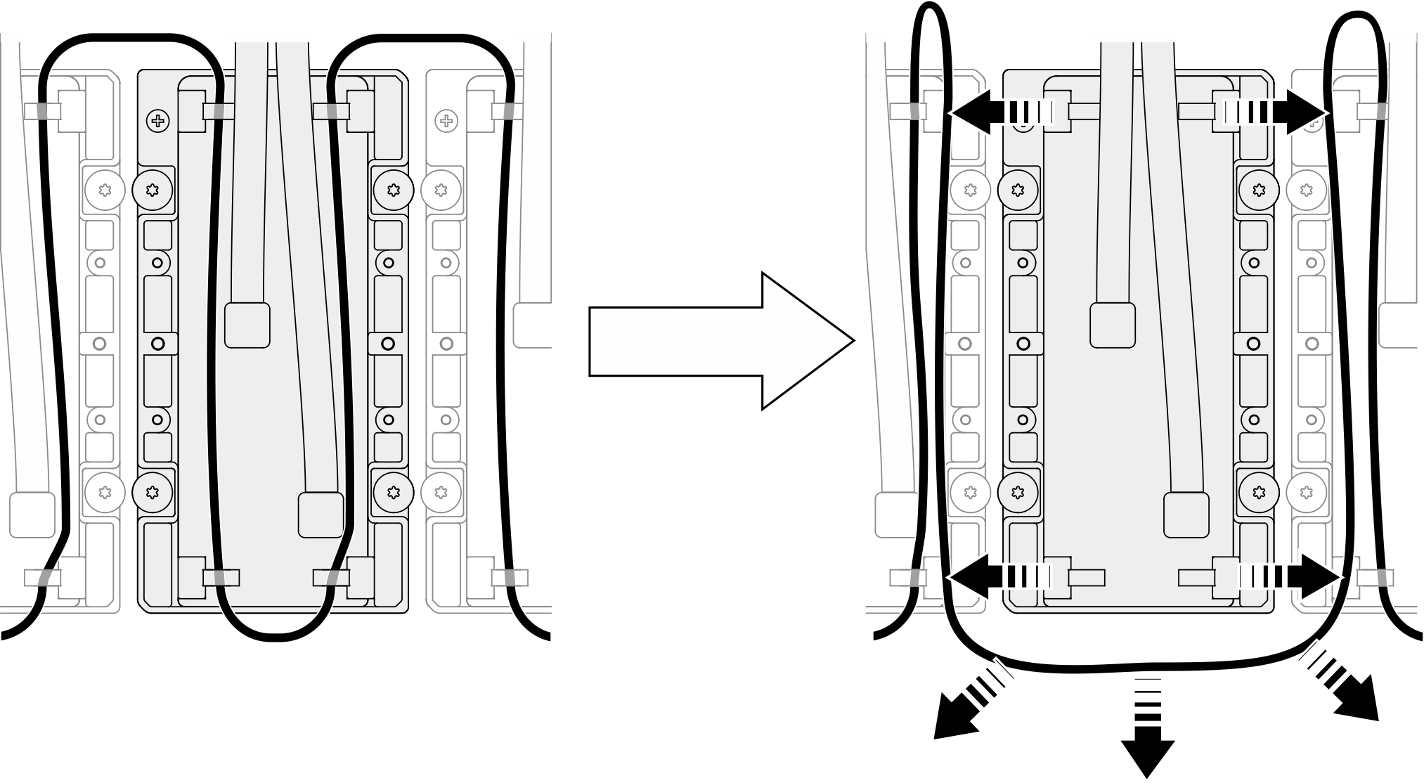
- Remove the leakage sensor module cable from the cable clips, route it away from the cold plate and onto the adjacent cold plate.Figure 5. Removing the leakage sensor module cable
- Loosen the screws by 360 degrees following the screw sequence:

 specified on the cold plate label, and fully loosen the four Torx T15 screws with a torque screwdriver set to the proper torque.Note
- Loosen the screws with a torque screwdriver set to the proper torque. For reference, the torque required for the screws to be fully loosen is 5.3±0.212 inch-pounds, 0.6±0.024 newton-meters.
- Ensure the captive screws are completely loosen before removing the cold plate module.
- Make sure to follow screw sequence to prevent cold plate tilting.
Figure 6. Removing the GPU cold plate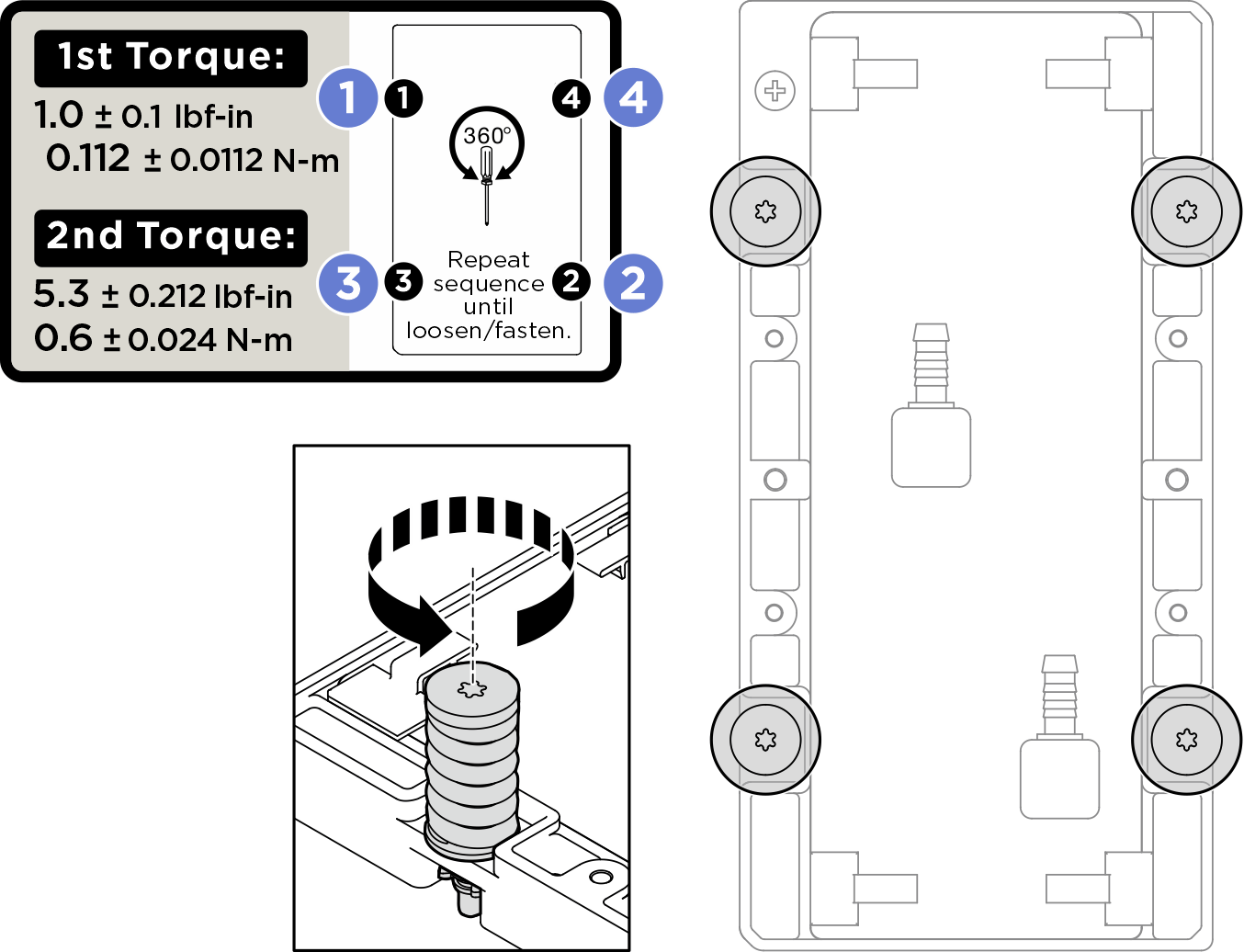 Note
NoteIf necessary, use the Tim breaker screw to separate the cold plate from the GPU. Ensure to fully loosen all the cold plate screws before fastening the TIM breaker screw.
- Open the lid of the TIM breaker screw.
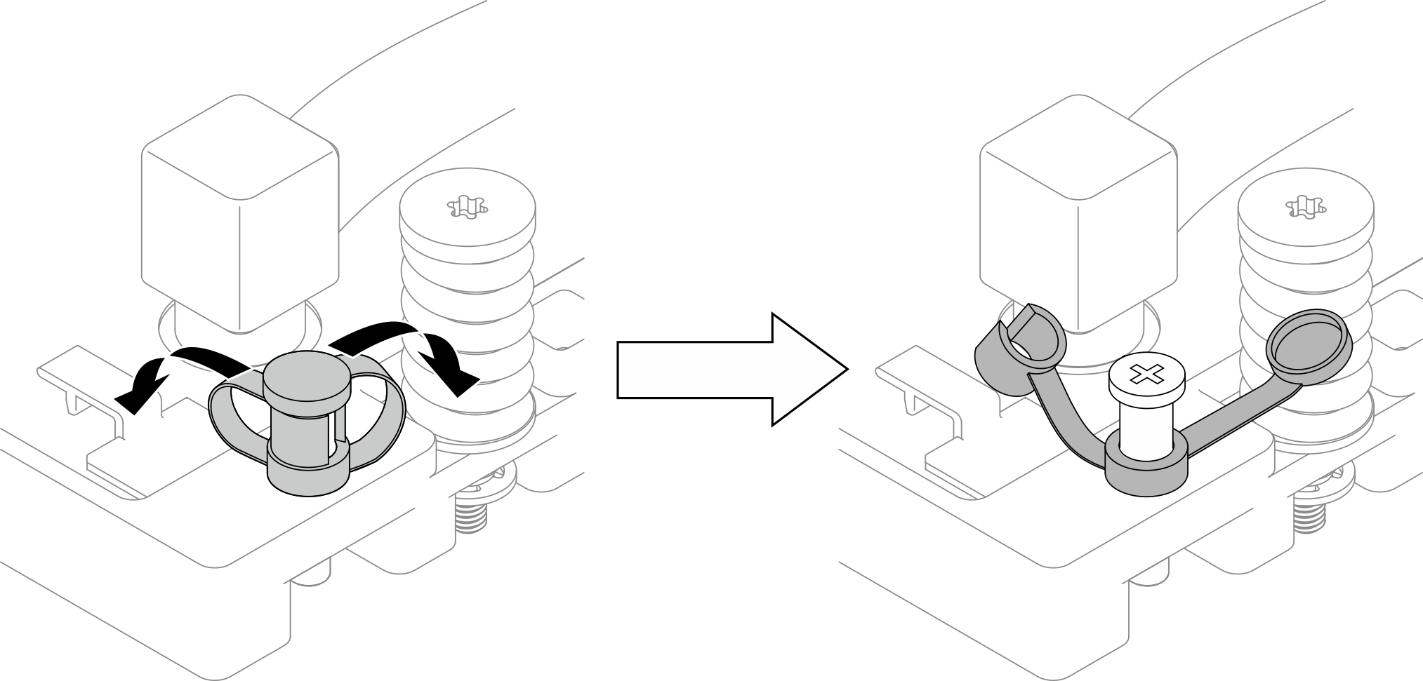
- Fasten the TIM breaker screw to separate the cold plate from the GPU.
After usage, return the TIM breaker screw to its original position.
- Loosen the TIM breaker screw to return it to its initial position.
- Close the lid. If the lid cannot be closed, the TIM breaker screw needs to be further loosened.
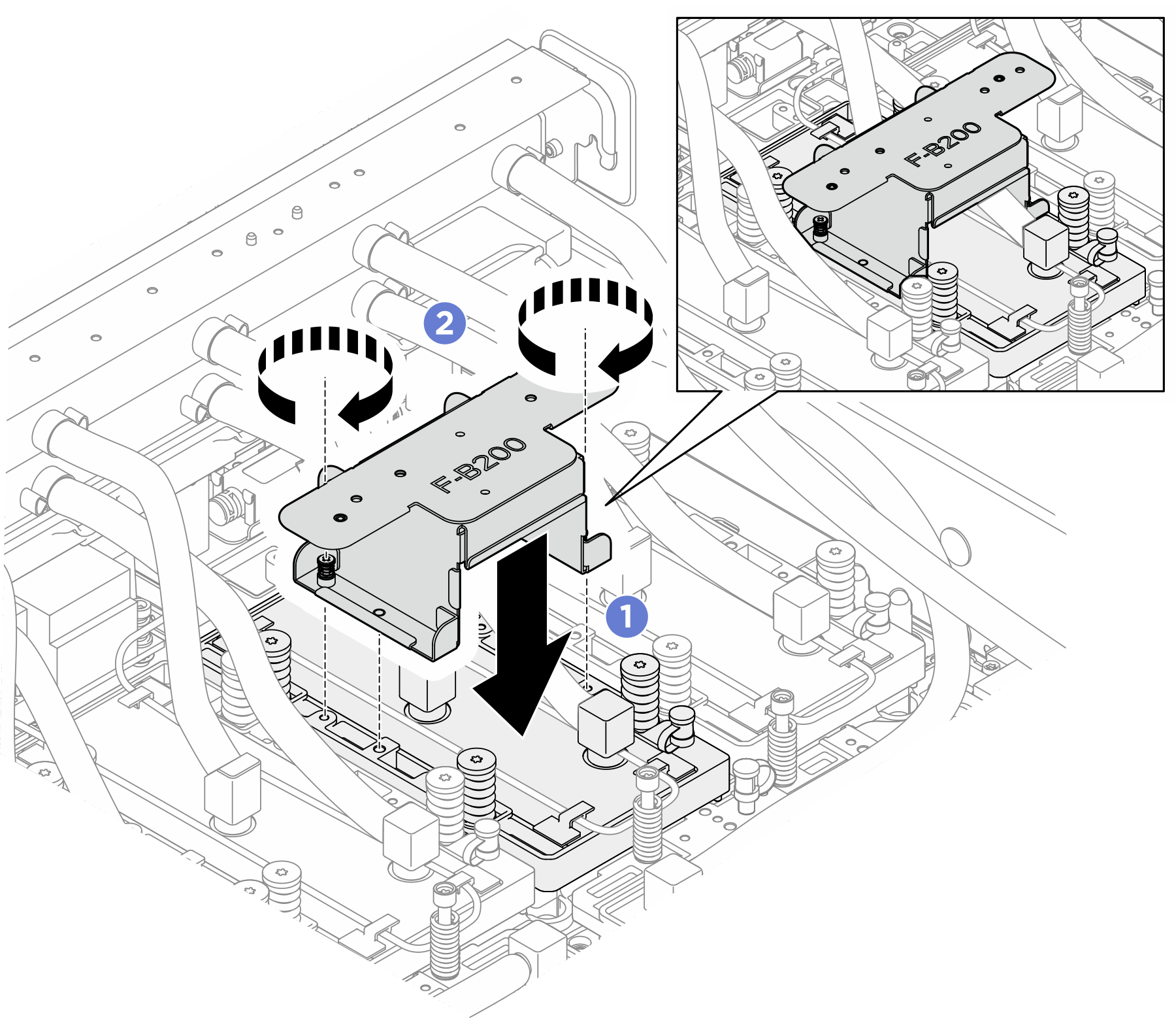
- Install the service bracket onto the front GPU cold plate. Ensure the service bracket is installed in the direction as illustrated, with the winged side facing the manifold.
- Align the two captive screws and guide pins at the bottom of the service bracket with the screw holes and guide holes on the GPU cold plate; then, lower it onto the cold plate.
- Fasten the two captive screws (PH1, 2 x M3, 0.5 newton-meters, 4.3 inch-pound) to secure the service bracket to the GPU cold plate.Figure 7. Installing the service bracket onto the GPU cold plate
 NoteAvoid pinching the leakage sensor module cable when installing the bracket.
- Install the service bracket and the GPU cold plate assembly onto the front B200 GPU cold plate module manifold.
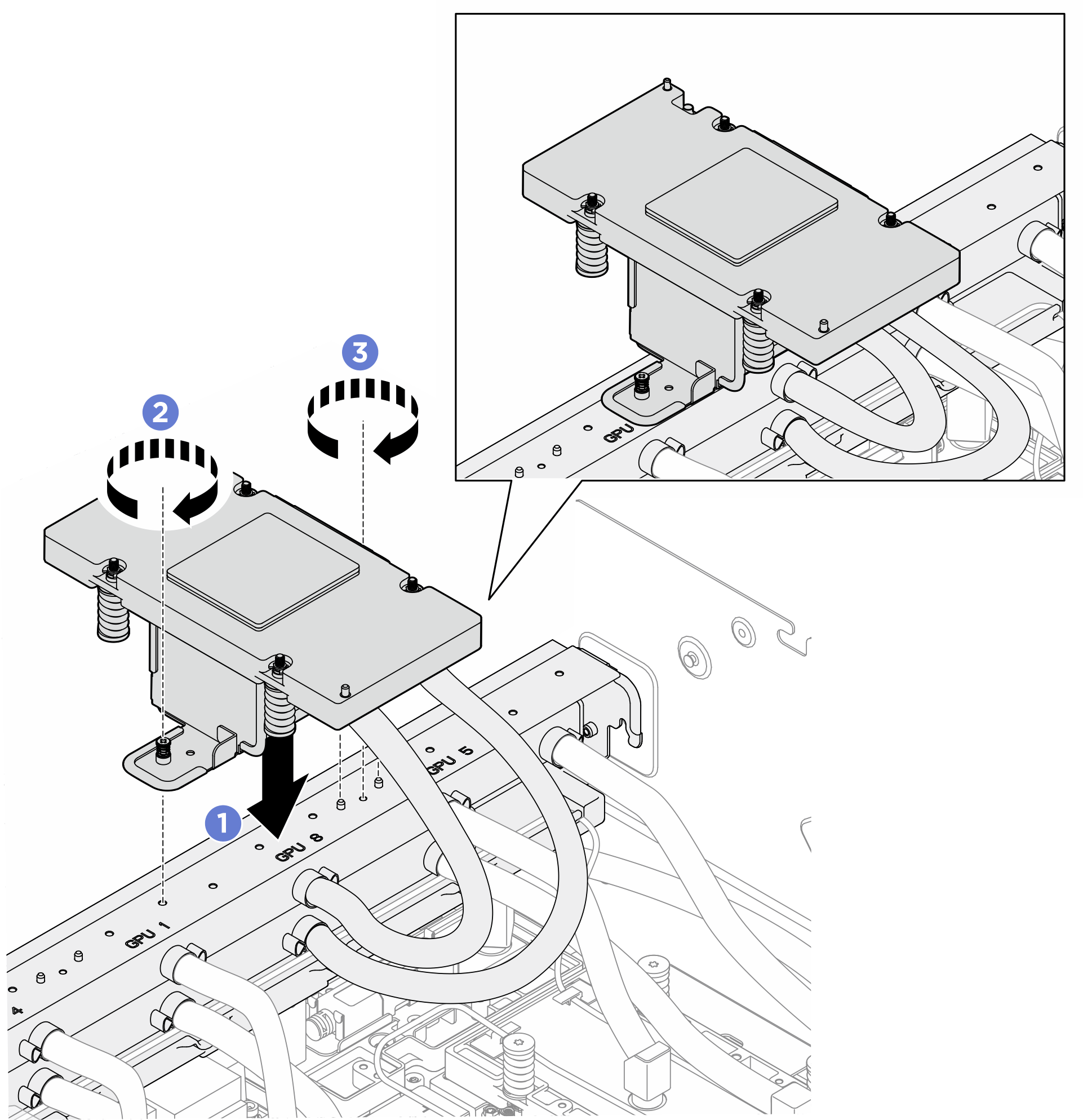
- Flip over the service bracket and the GPU cold plate assembly; then, align the two captive screws and two guide pins with the screw holes and guide holes on the manifold.NoteEnsure that the hoses are not bent inward to avoid stress damage to the joints.
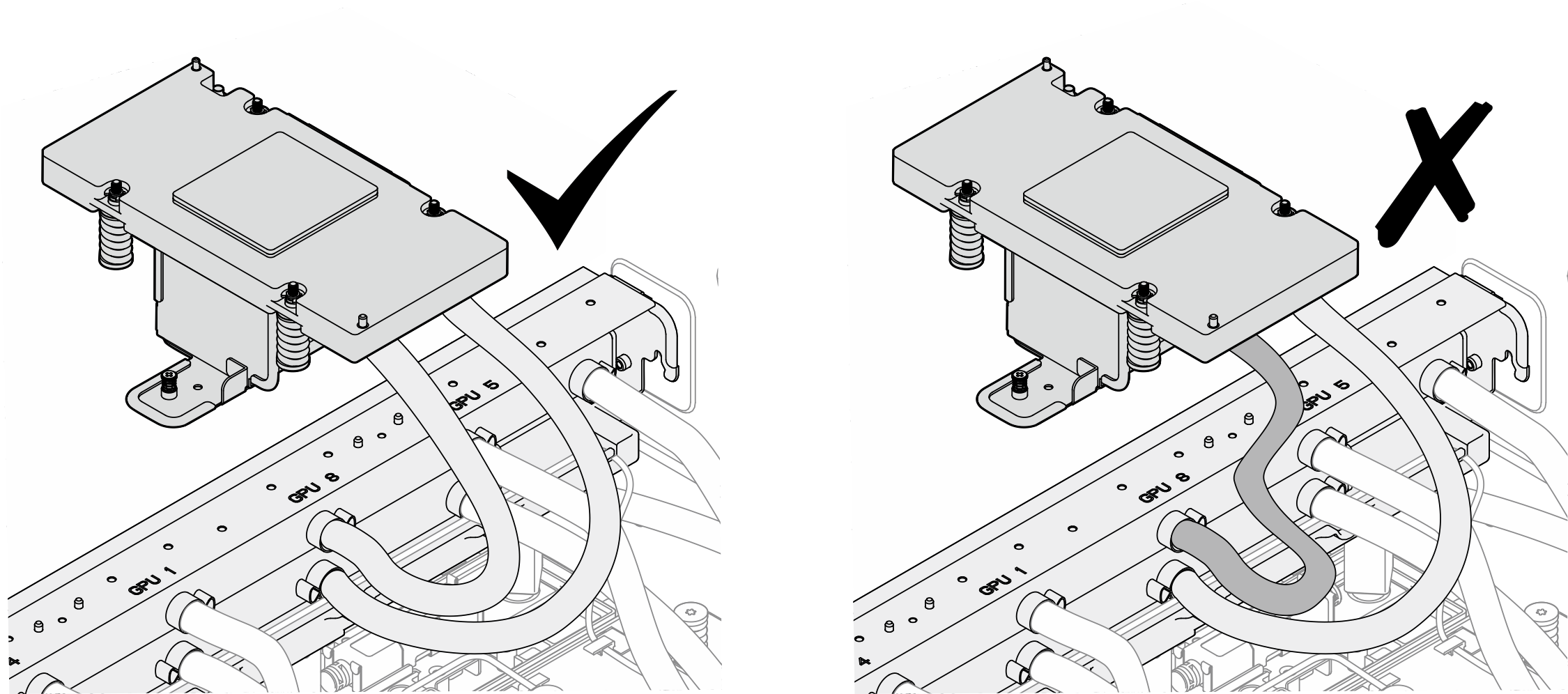
- First, tighten the captive screw (PH1, 1 x M3, 0.5 newton-meters, 4.3 inch-pound) that is on the side without guide pins. The screw and pin locations are different for the four front GPUs. In the illustration GPU 8 is used as an example. Ensure to check the screw and pin locations before tightening the first screw.
- Then, tighten the captive screw (PH1, 1 x M3, 0.5 newton-meters, 4.3 inch-pound) that is on the side with guide pins.Figure 8. Installing the service bracket and the GPU cold plate assembly
 NoteEnsure to install the service bracket and GPU cold plate assembly in the screw holes and guide holes corresponding to the specific GPU slot number.Figure 9. Service bracket and GPU cold plate assembly installation location
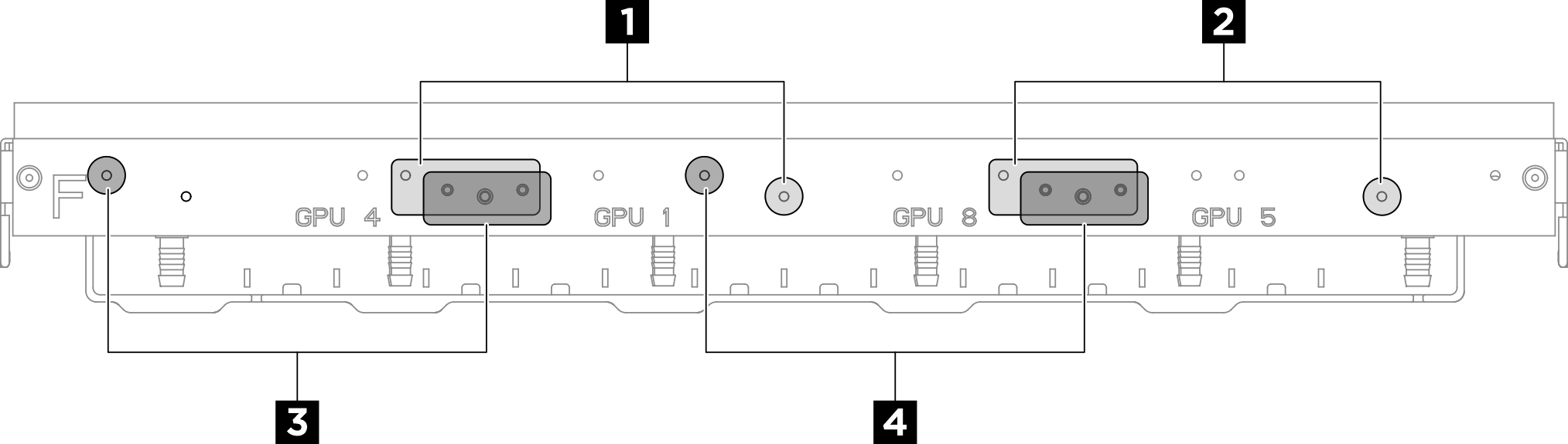
Table 1. GPU cold plate and service bracket assembly installation location Installation location GPU slot number 1 GPU 1 2 GPU 5 3 GPU 4 4 GPU 8
- Immediately clean the PCM and putty pads off from the GPU with alcohol cleaning pads. Gently clean the PCM and putty pads to avoid GPU damages.Attention
It is recommended to clean the PCM while it is in liquid state.
The electrical components around the die on the GPUs are extremely delicate. When removing the PCM and cleaning the GPU die, avoid touching the electrical components to prevent damage.
Figure 10. Cleaning PCM and putty pads off from the GPU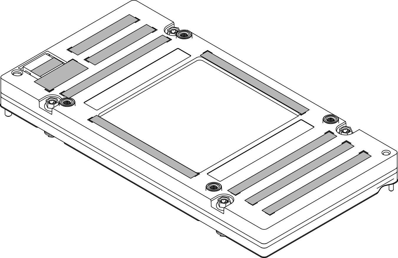
- With alcohol cleaning pads, wipe off any remaining putty pad and PCMs from the GPU cold plate.Figure 11. Wiping PCM and putty pads off from the cold plate
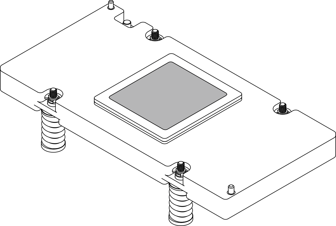
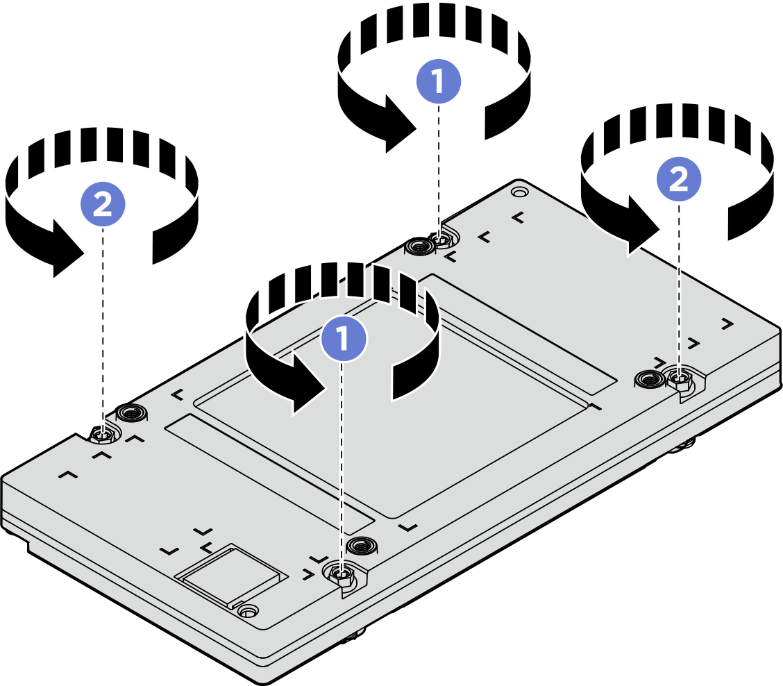
- Remove the GPU. Attach the Torx T15 200mm extension bit to a torque screwdriver. Unfasten the four Torx T15 screws in the sequence shown in the illustration below with the screwdriver set to the proper torque.
- Set the torque screwdriver to 0.81 newton-meters, 7.17 inch-pounds to loosen the screws in the sequence of >>>.Figure 12. Removing the GPU
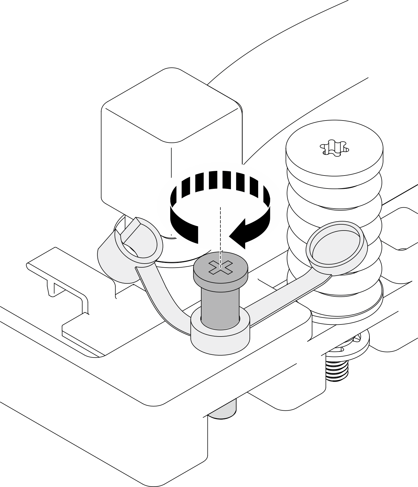
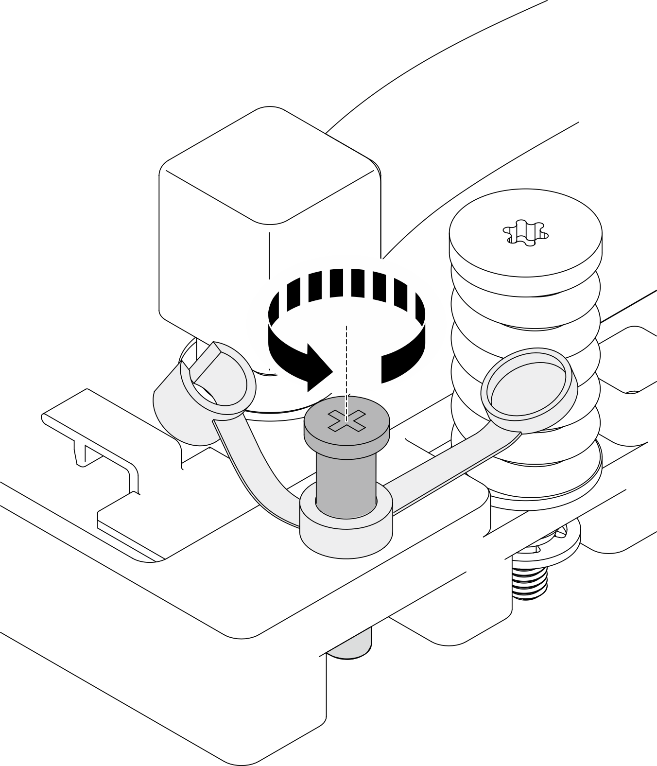
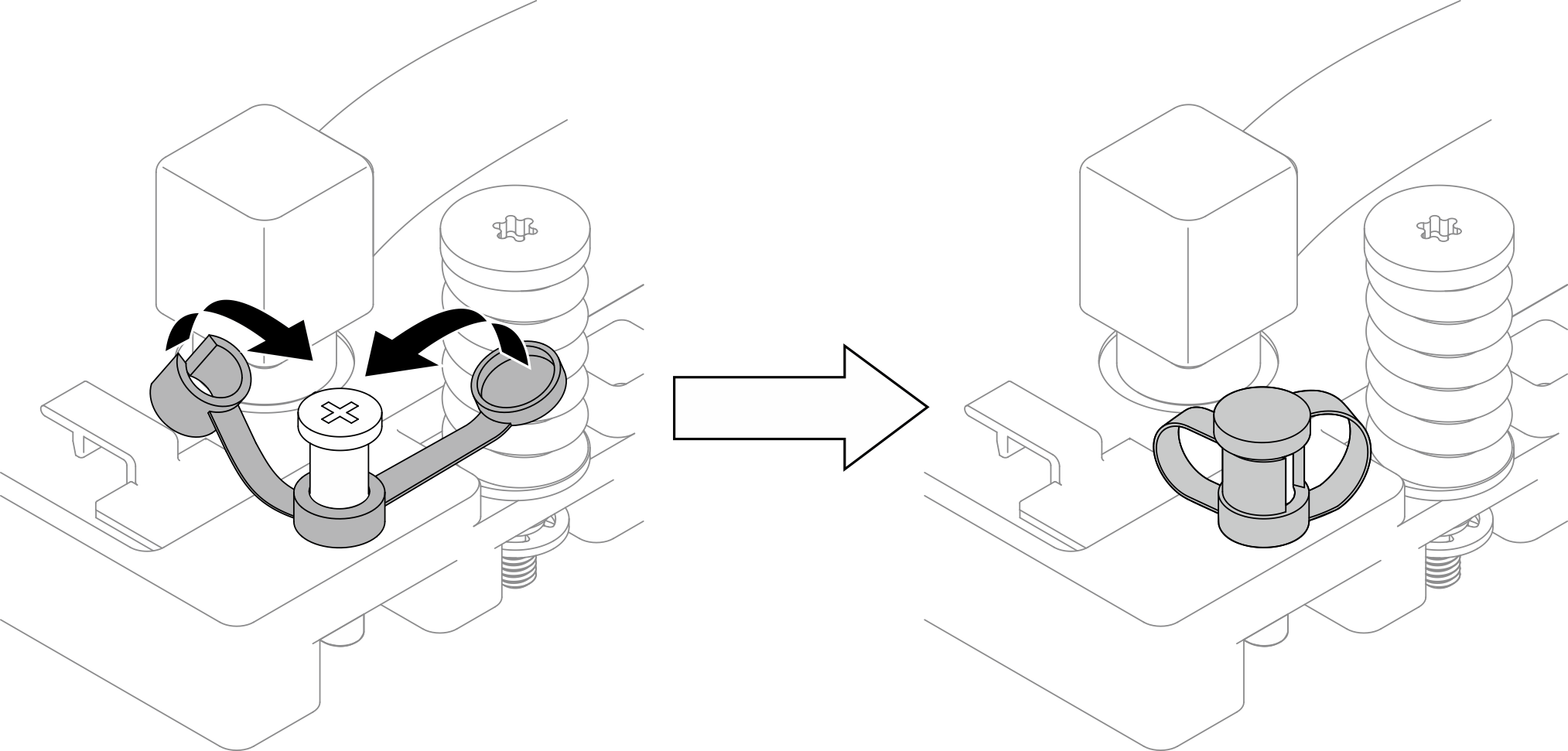
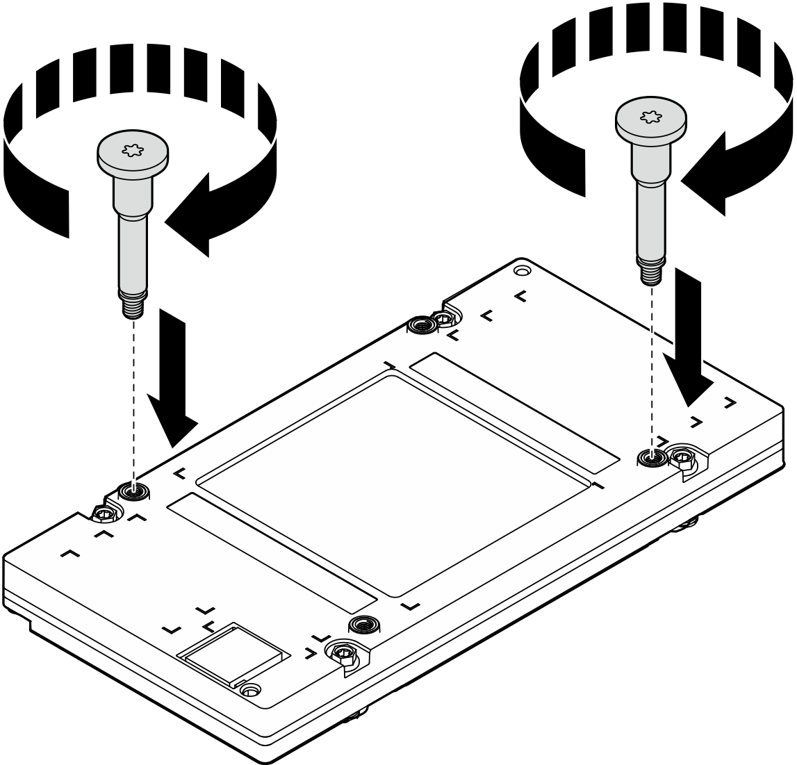
- Install the two GPU screw handles diagonally. Align the screw handles to the cold plate screw slots; then fasten the screw handles by hand.Figure 13. Installing the GPU screw handles
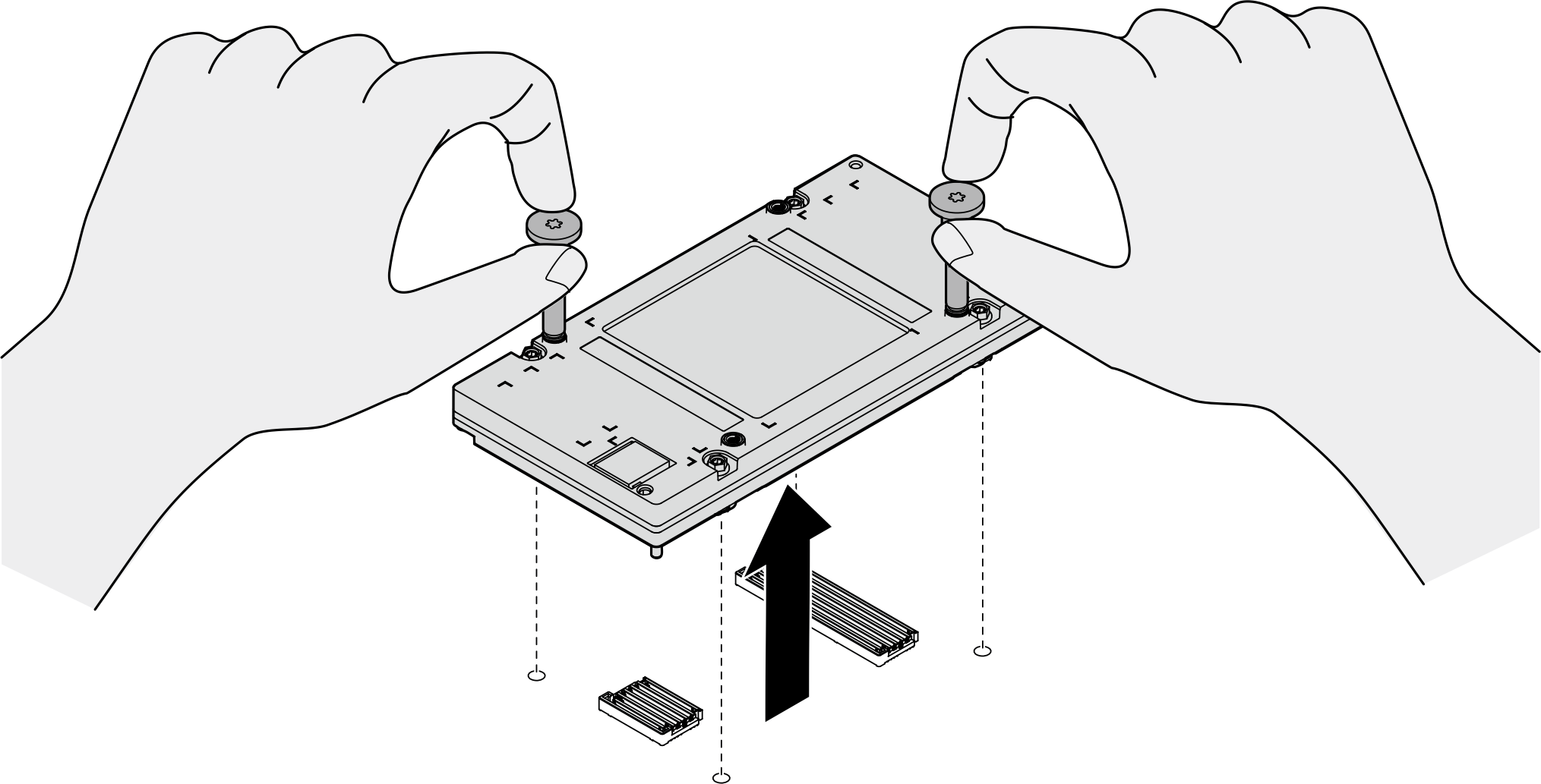
- Hold the GPU screw handles to remove the GPU from the GPU baseboard.Figure 14. Removing the GPU
- Carefully lay the GPU on a flat, static protective surface. Remove the two screw handles by loosening them by hand.Figure 15. Removing the GPU screw handles
- Set the torque screwdriver to 0.81 newton-meters, 7.17 inch-pounds to loosen the screws in the sequence of
After you finish
- Install a replacement unit. See Install a front B200 GPU.
- If you are instructed to return the component or optional device, follow all packaging instructions, and use any packaging materials for shipping that are supplied to you.
Give documentation feedback