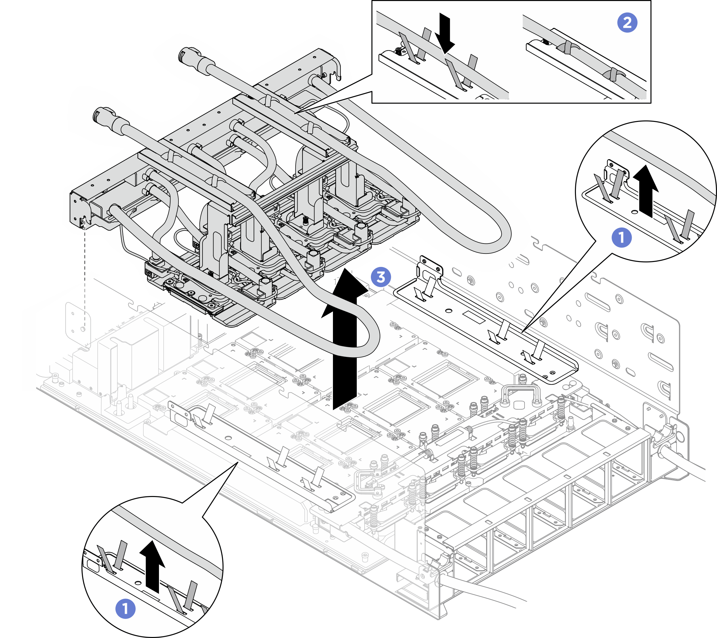
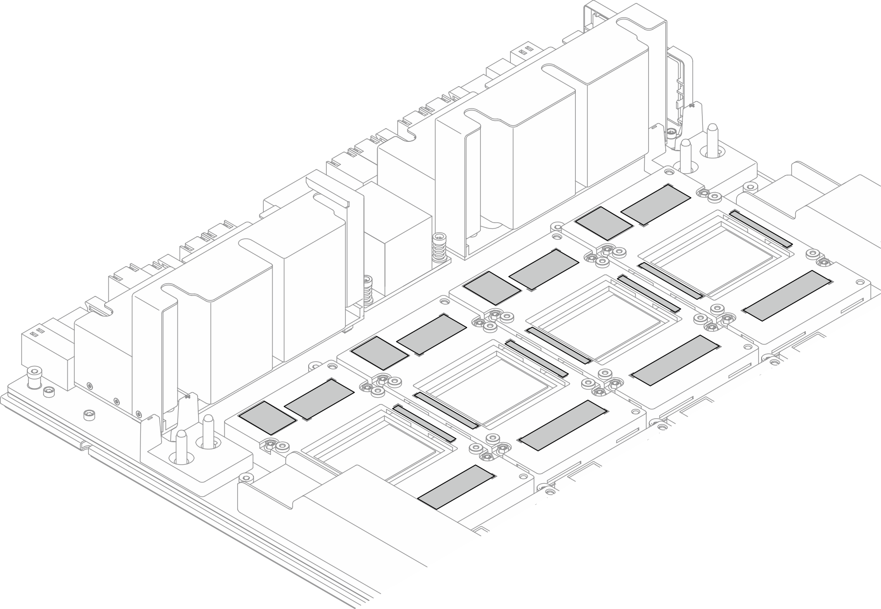
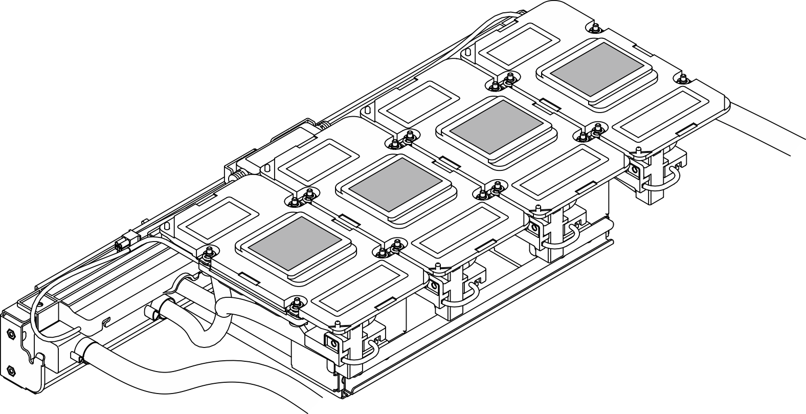
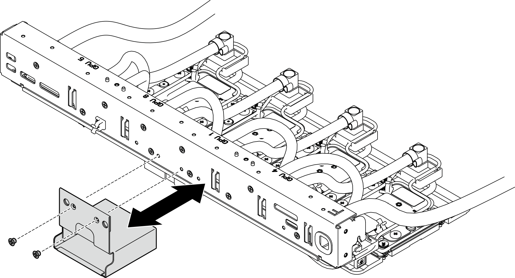
Remove the front H100/H200 GPU cold plate module
Follow instructions in this section to remove the front H100/H200 GPU cold plate module. The procedure must be executed by a trained technician.
About this task
Attention
- Read Installation Guidelines and Safety inspection checklist to ensure that you work safely.
- Power off the server and peripheral devices and disconnect the power cords and all external cables. See Power off the server.
- If the server is installed in a rack, slide the server out on its rack slide rails to gain access to the top cover, or remove the chassis from the rack. See Remove the server from rack.
- Two people and one lifting device on site that can support up to 400 lb (181 kg) are required to perform this procedure. If you do not already have a lifting device available, Lenovo offers the Genie Lift GL-8 material lift that can be purchased at Data Center Solution Configurator. Make sure to include the Foot-release brake and the Load Platform when ordering the Genie Lift GL-8 material lift.
- A torque screwdriver is available for request if you do not have one at hand.
Note
Make sure you have the required tools listed below available to properly replace the component:
- Torx T10 head screwdriver
- Torx T15 head screwdriver
- Phillips #1 head screwdriver
- Phillips #2 head screwdriver
- Flat head screwdriver
- Alcohol cleaning pad
- H100/H200 PCM kit
- SR780a V3 H100/H200 water loop putty pad kit
- SR780a V3 H100/H200 water loop service kit
- H100/H200 GPU service fixture kit
Important
Putty pad/phase change material (PCM) replacement guidelines
- Before replacing the putty pad/PCM, gently clean the hardware surface with an alcohol cleaning pad.
- Hold the putty pad/PCM carefully to avoid deformation. Make sure no screw hole or opening is blocked by the putty pad/PCM.
- Do not use expired putty pad/PCM. Check the expiry date on putty pad/PCM package. If the putty pads/PCM are expired, acquire new ones to properly replace them.
The following illustration shows the GPU numbering and corresponding slot numbering in XCC.
Figure 1. GPU numbering
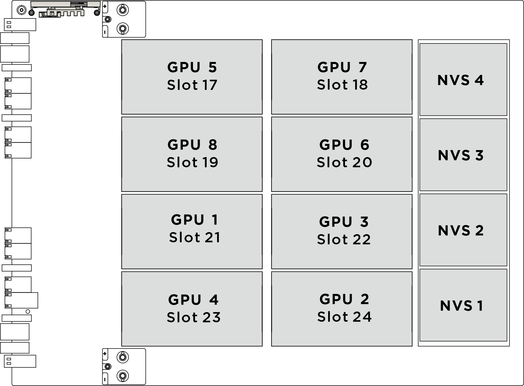

| Physical GPU socket | Slot numbering in XCC | Module ID in nvidia-smi |
|---|---|---|
SXM 1 | Slot 21 | 1 |
SXM 2 | Slot 24 | 2 |
SXM 3 | Slot 22 | 3 |
SXM 4 | Slot 23 | 4 |
SXM 5 | Slot 17 | 5 |
SXM 6 | Slot 20 | 6 |
SXM 7 | Slot 18 | 7 |
SXM 8 | Slot 19 | 8 |
The following illustration shows the components for front H100/H200 GPU cold plate module.
Figure 2. Front H100/H200 GPU cold plate module components identification
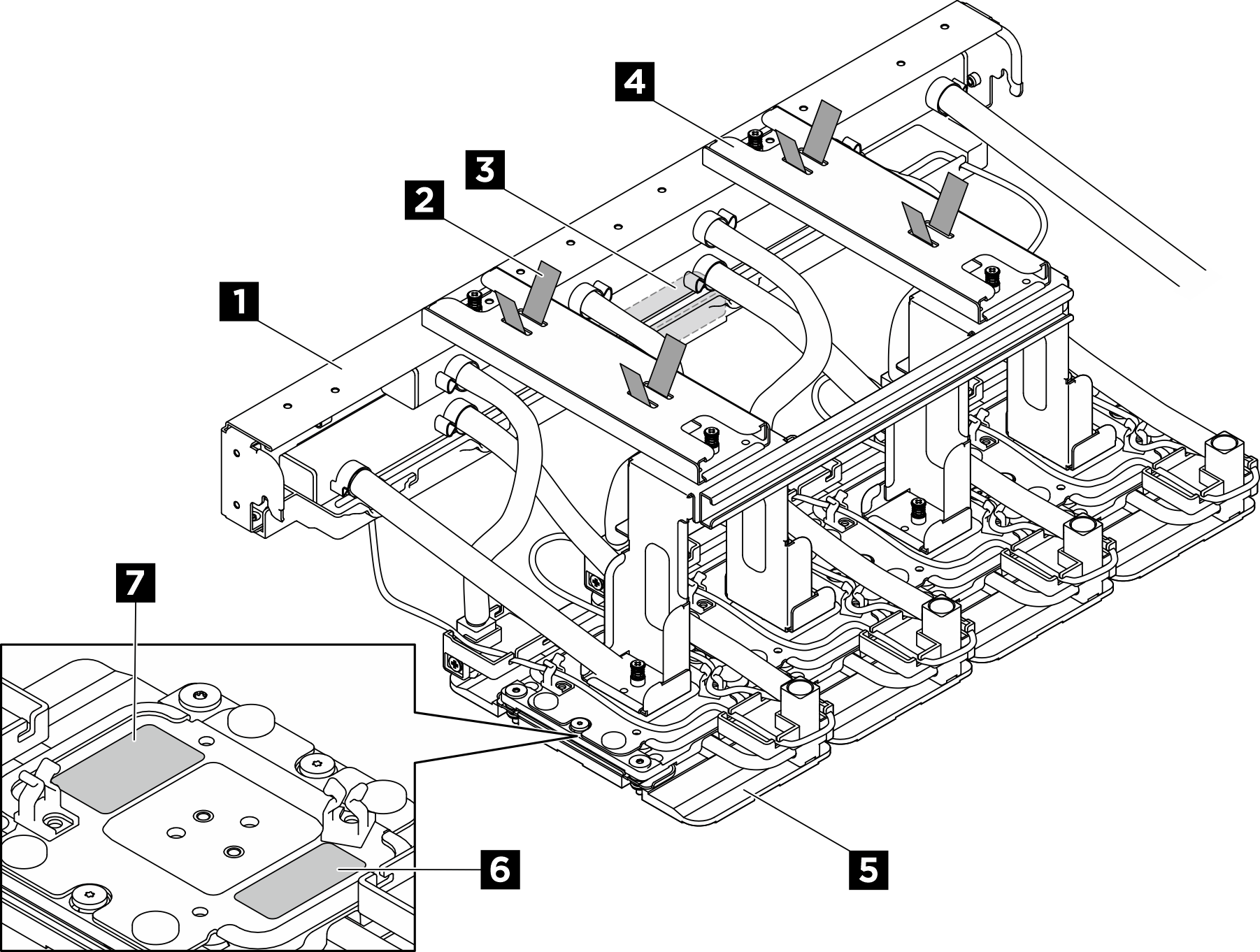

| 1 Manifold | 2 Hose tie |
| 3 Leakage sensor module | 4 Shipping bracket |
| 5 GPU cold plate | 6 GPU slot number label |
| 7 GPU cold plate screw torque label |
Procedure
After you finish
- Install a replacement unit. See Install the front H100/H200 GPU cold plate module.
- If you are instructed to return the component or optional device, follow all packaging instructions, and use any packaging materials for shipping that are supplied to you.
Give documentation feedback
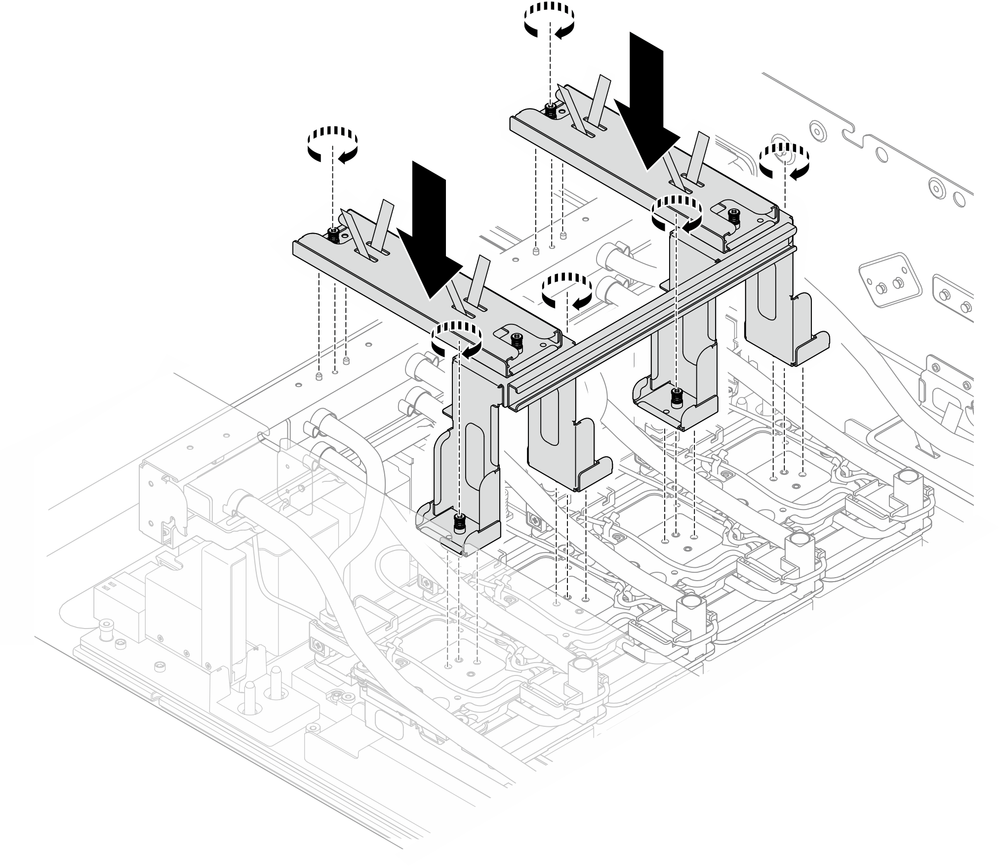
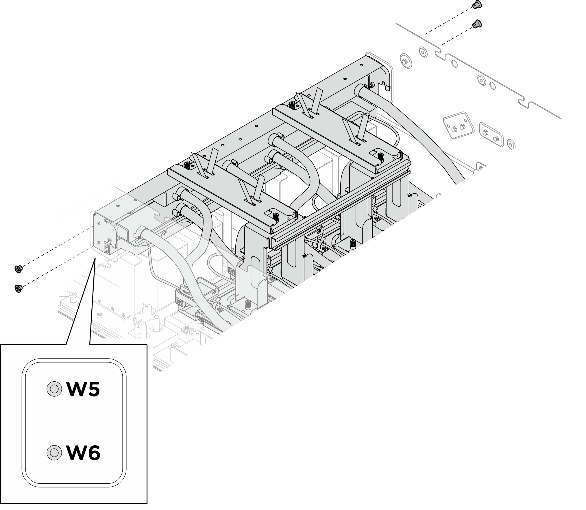
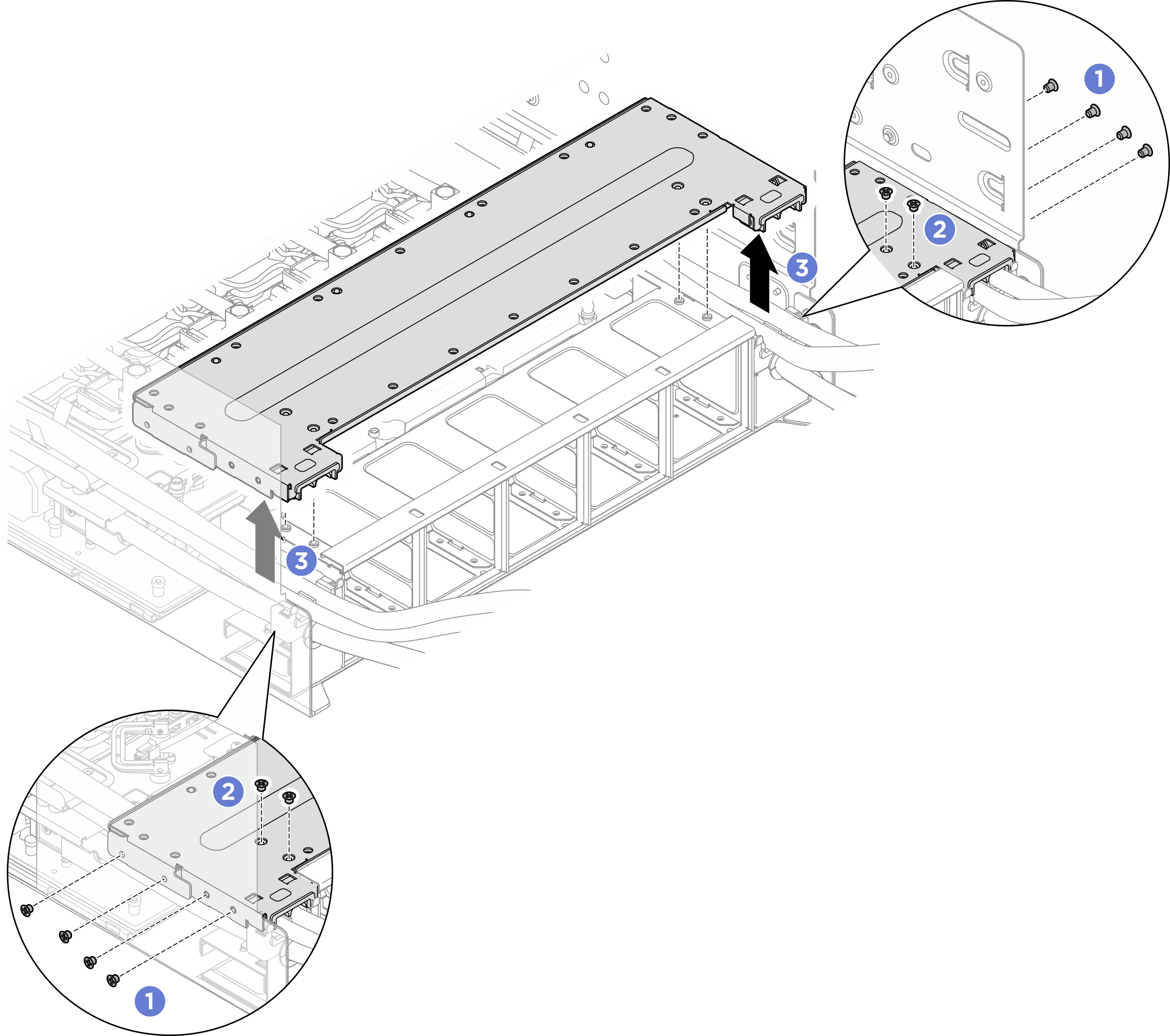
 Unfasten the eight M3 screws that secure the rear fan cage support bracket to the the chassis.
 Unfasten the four M3 screws that secure the rear fan cage support bracket to the fan cage.
 Grasp the rear fan cage support bracket to lift it from the fan cage.
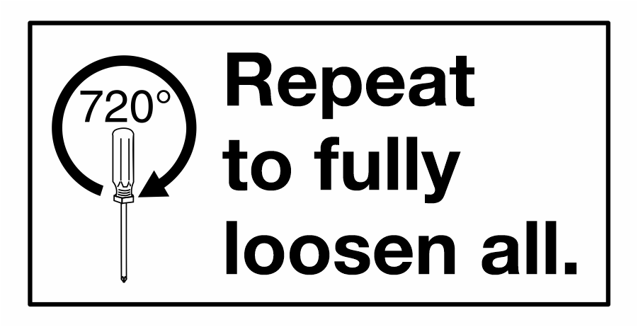
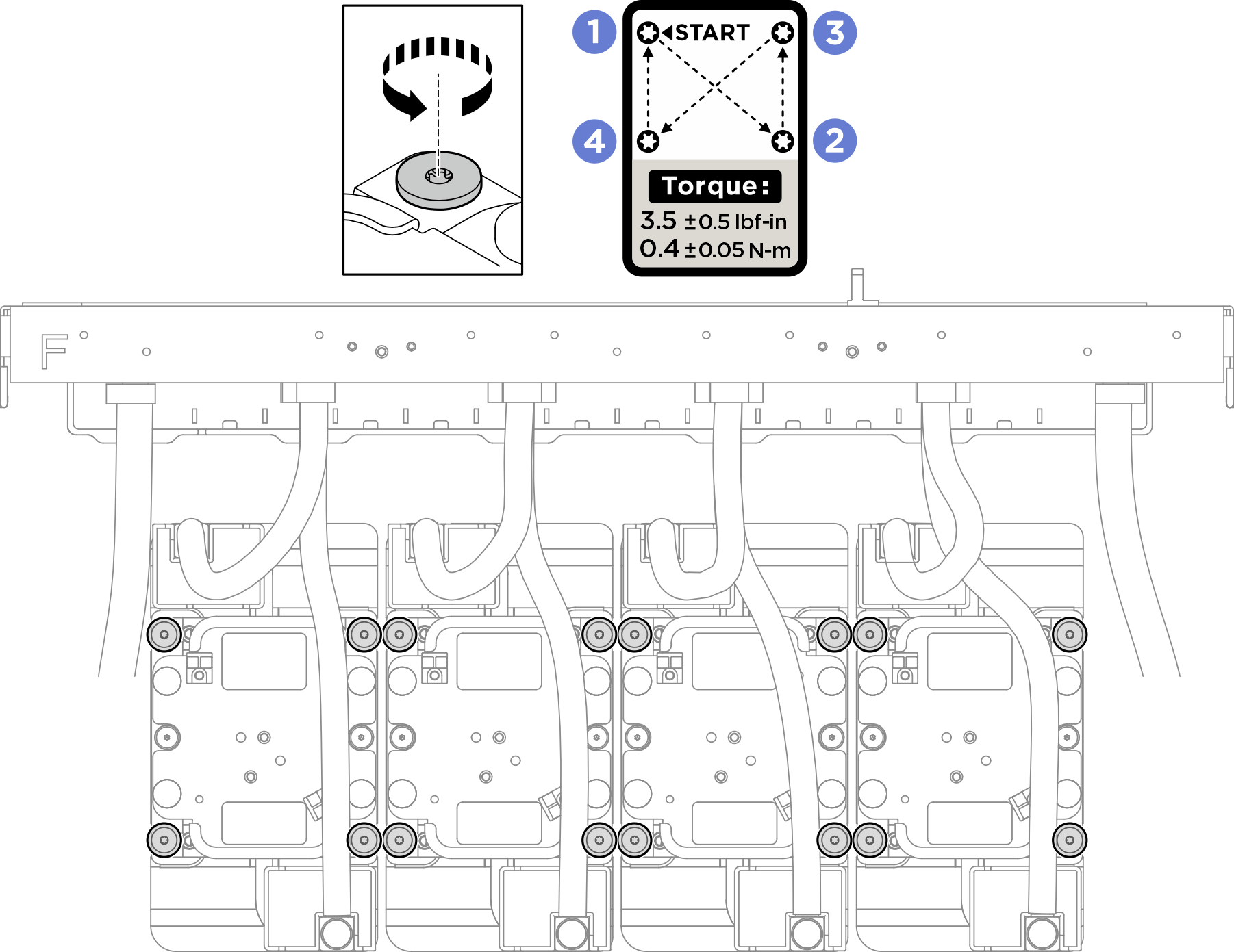
 specified on the cold plate label, and fully loosen the sixteen Torx T10 screws with a torque screwdriver set to the proper torque.