PCIe riser A cable routing
Follow the instructions in this section to learn how to do cable routing for the PCIe riser A.
Note
Connections between connectors; 1↔1, 2↔2, 3↔3, ... n↔n
The Cable PN or FRU PN can be found on the label attached to the cable.
When routing the cables, make sure that all cables are routed appropriately through the corresponding cable guides and cable clips.
A label on each signal cable indicates the connection source and destination. This information is in the format RY-X and P Z. Where Y indicates the PCIe riser number, X indicates the connector on the riser card, and Z indicates the connector on the system board assembly.
Choose the routing plan according to the server model.
Server model with 2.5-inch bays
Figure 1. Cable routing for the PCIe riser A (2.5-inch server)
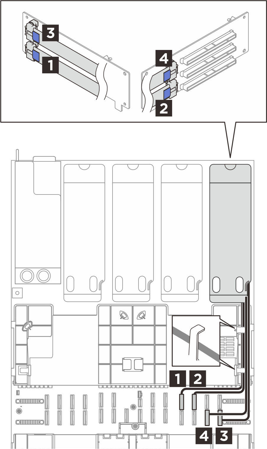
| From (PCIe riser) | To (System board assembly) | Cable |
|---|---|---|
1 R1 | 1 P22 | MCIO x8 to Swift x8 (580 mm, flat 140 mm) |
2 R2 | 2 P23 | MCIO x8 to Swift x8 (420 mm) |
3 R3 | 3 P14 | MCIO x8 to Swift x8 (500 mm, flat 140 mm) |
4 R4 | 4 P13 | MCIO x8 to Swift x8 (420 mm) |
Server model with E3.S bays
Figure 2. Cable routing for the PCIe riser A (E3.S server)
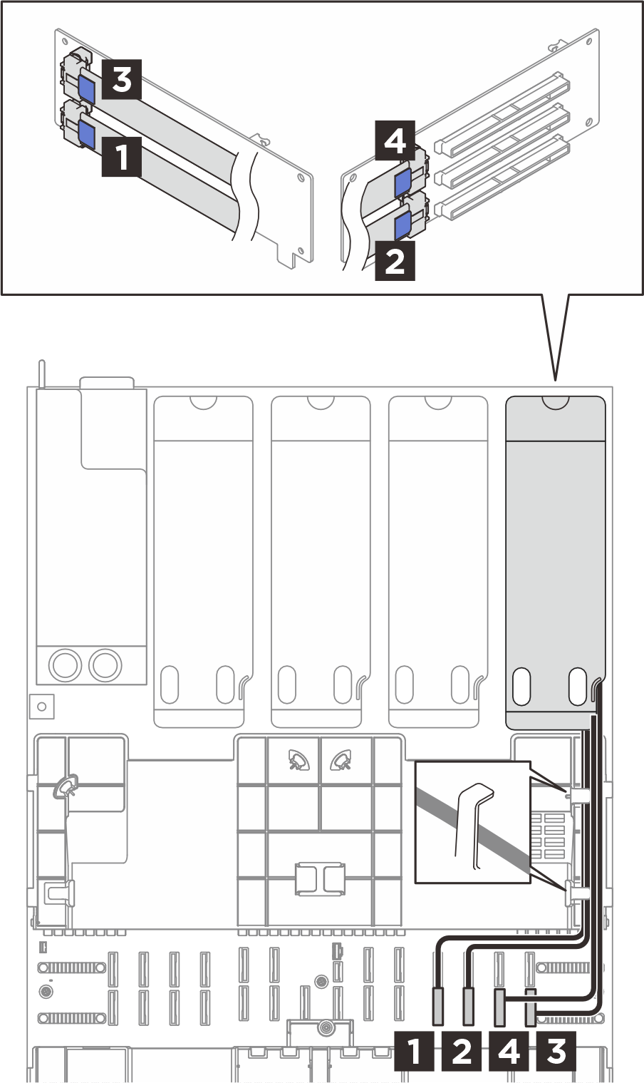
| From (PCIe riser) | To (System board assembly) | Cable |
|---|---|---|
1 R1 | 1 P11 | MCIO x8 to Swift x8 (580 mm, flat 140 mm) |
2 R2 | 2 P12 | MCIO x8 to Swift x8 (420 mm) |
3 R3 | 3 P14 | MCIO x8 to Swift x8 (500 mm, flat 140 mm) |
4 R4 | 4 P13 | MCIO x8 to Swift x8 (420 mm) |
Give documentation feedback