Install the PCIe riser
Follow the instructions in this section to install the PCIe riser.
About this task
Read Installation Guidelines and Safety inspection checklist to ensure that you work safely.
Power off the server and peripheral devices and disconnect the power cords and all external cables. See Power off the server.
Prevent exposure to static electricity, which might lead to system halt and loss of data, by keeping static-sensitive components in their static-protective packages until installation, and handling these devices with an electrostatic-discharge wrist strap or other grounding system.
Go to Drivers and Software download website for ThinkSystem SR860 V3 to see the latest firmware and driver updates for your server.
Go to Update the firmware for more information on firmware updating tools.
Install PCIe riser 3
Procedure
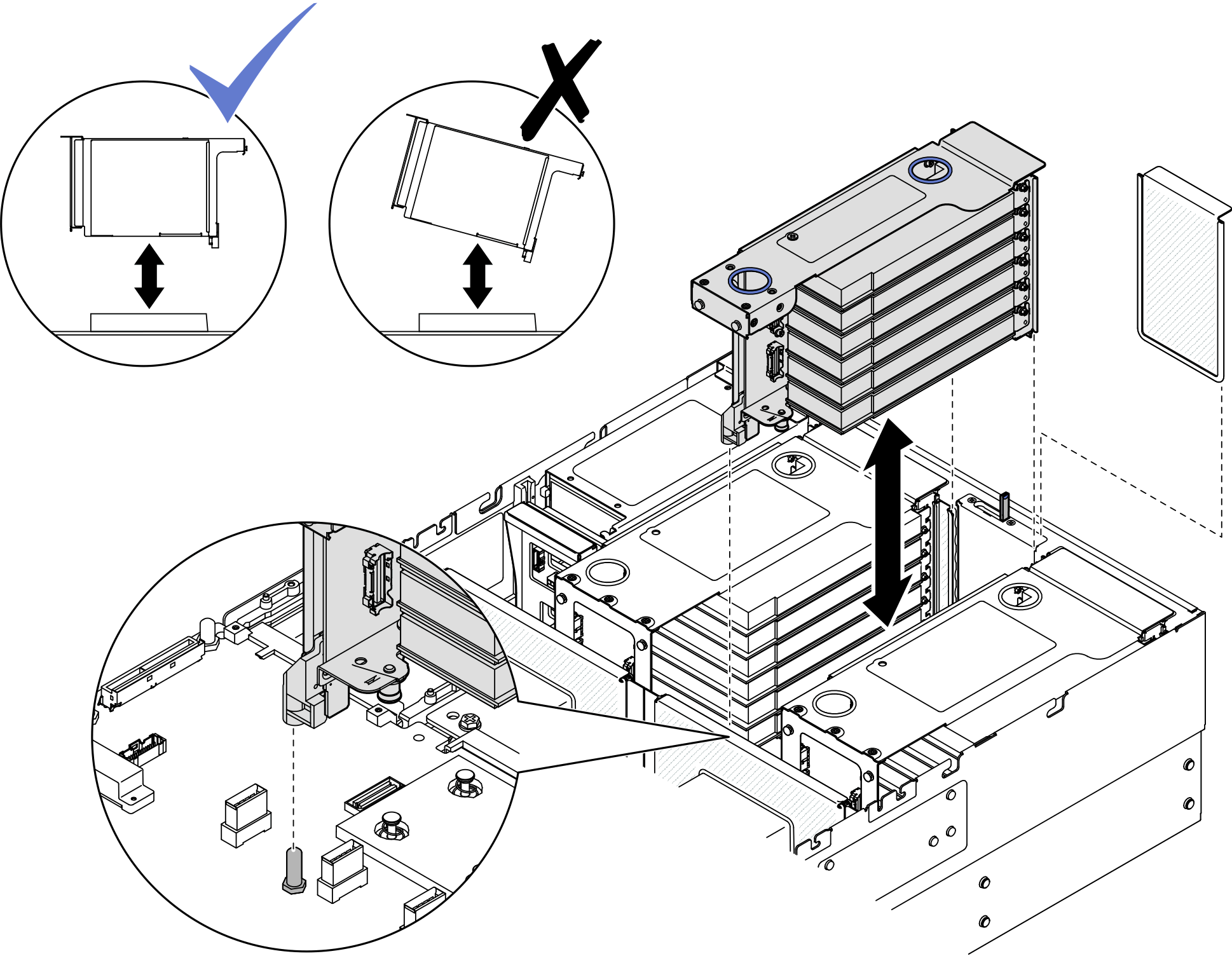
- Install PCIe riser 3.Figure 1. Installing PCIe riser 3
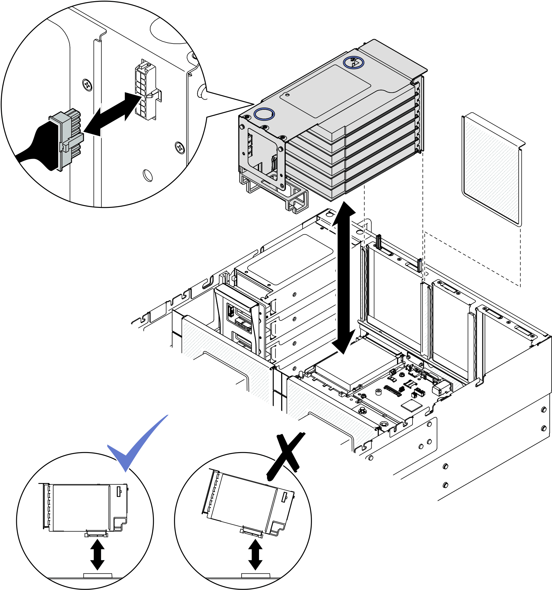
- For six slot FH risers, route all internal cables through the cable retainer as shown below.
RAID/HBA to flash power module, backplane 2 or 5 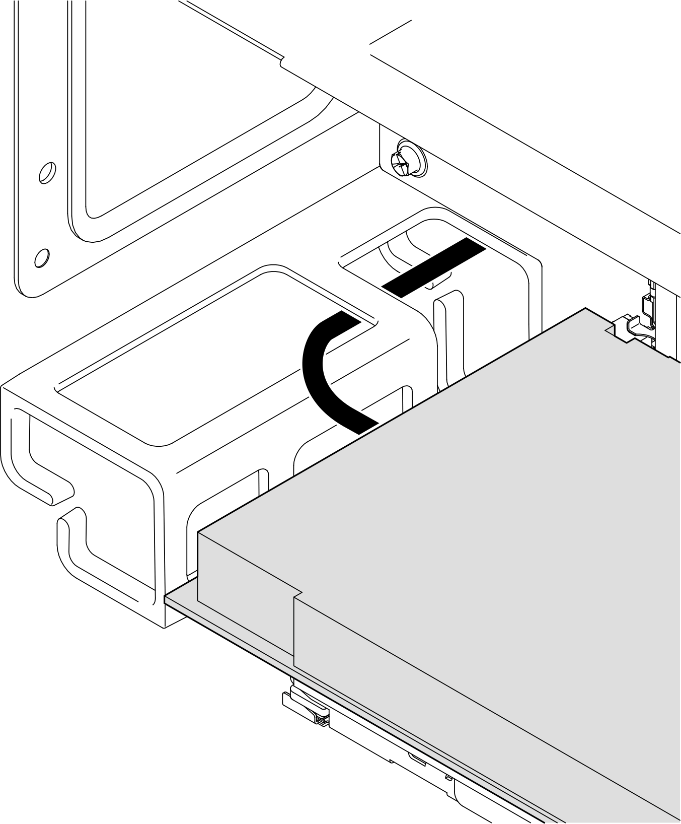
RAID/HBA to backplane 1, 3, 4, or 6 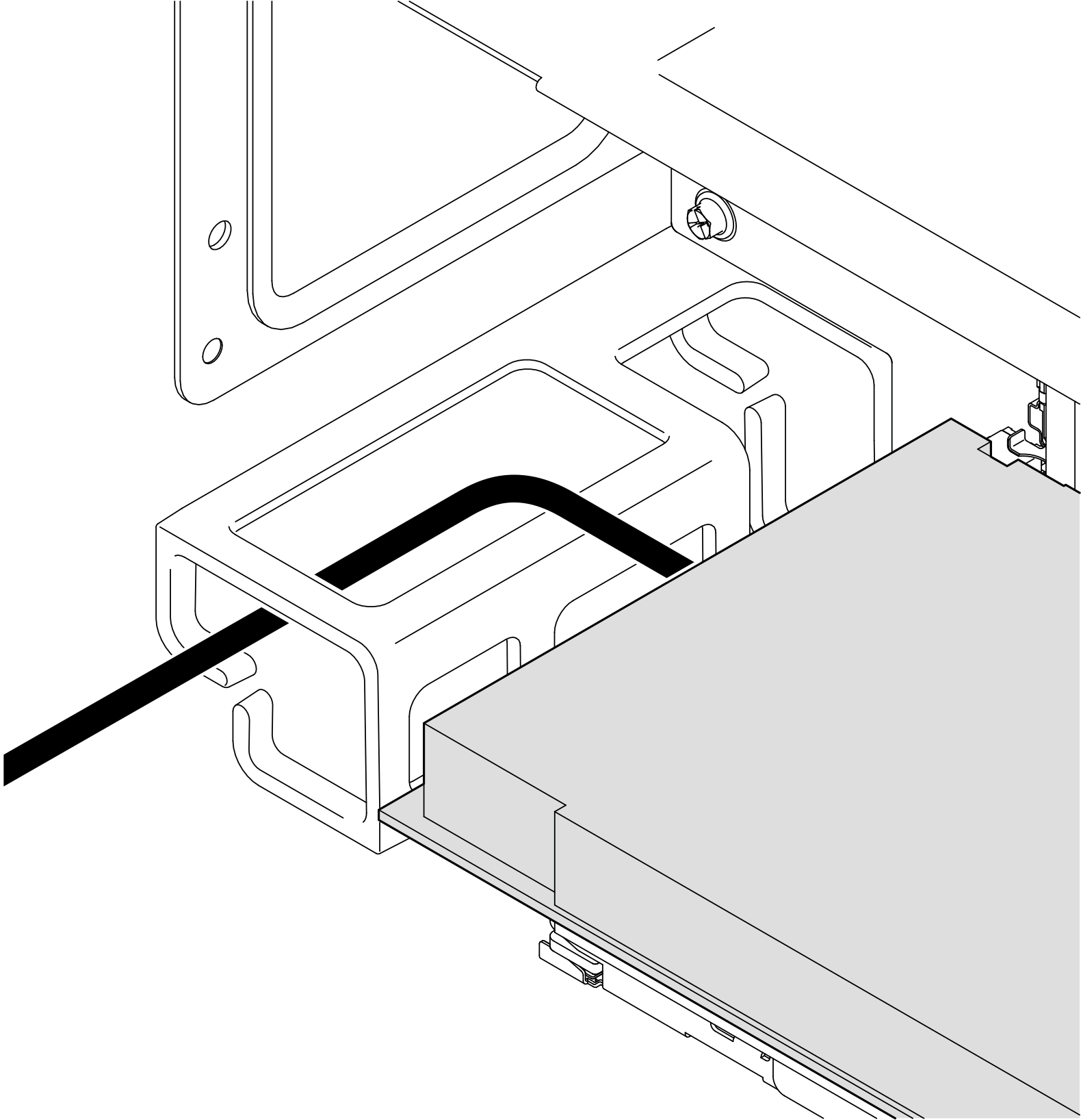
- For six slot FH risers, route all internal cables through the cable retainer as shown below.
- If a 7mm drive cage is installed in PCIe riser 3, connect the 7mm drive cables and reinstall PCIe riser 1.Figure 2. Installing PCIe riser 1
- For six slot FH risers, route all internal cables through the cable retainer as shown below.
RAID/HBA to backplane 1, 3, 4, or 6 RAID/HBA to flash power module, backplane 2 or 5
- For six slot FH risers, route all internal cables through the cable retainer as shown below.
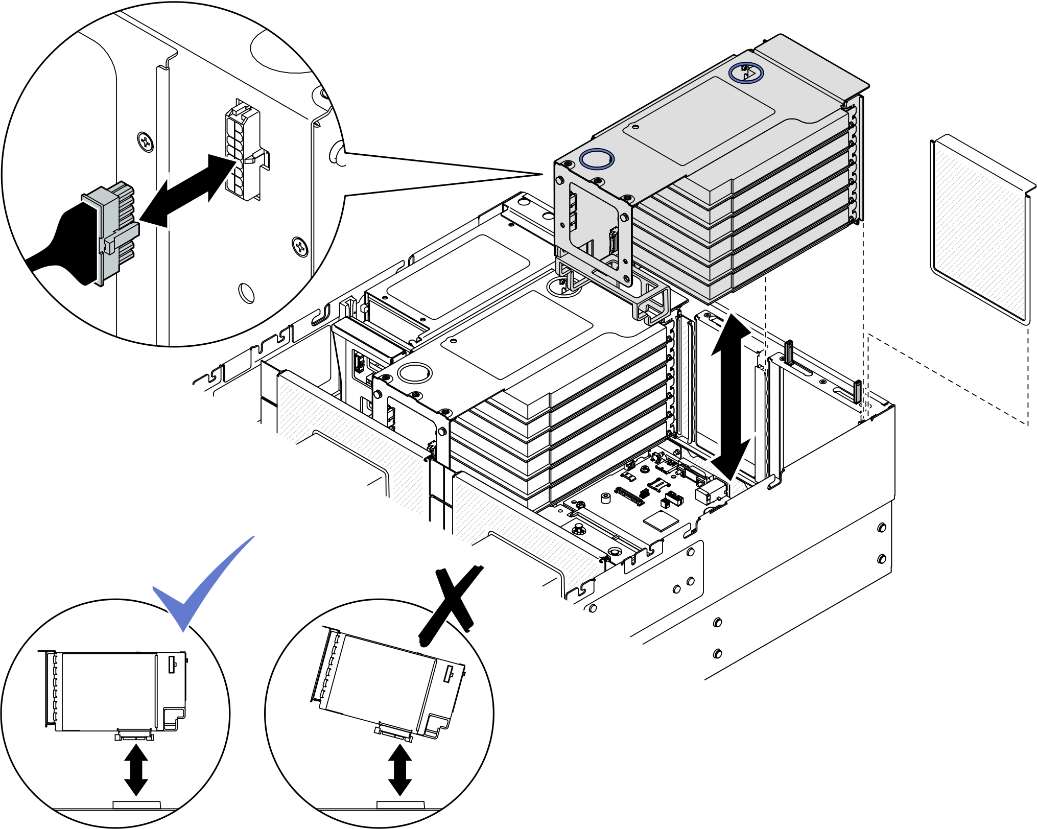
- Install PCIe riser 2.Figure 3. Installing PCIe riser 2
- Connect all internal cables to the PCIe adapters.
- Align and install the PCIe riser until it rests firmly on top of the kickstand.
- Connect the PCIe riser 2 assembly cables to the system board assembly. See PCIe riser 2 cable routing for more information on the internal cable routing.
Install PCIe riser 1
Procedure
- Install PCIe riser 1.Figure 4. Installing PCIe riser 1
- For six slot FH risers, route all internal cables through the cable retainer as shown below.
RAID/HBA to backplane 1, 3, 4, or 6 RAID/HBA to flash power module, backplane 2 or 5
- For six slot FH risers, route all internal cables through the cable retainer as shown below.
- Install PCIe riser 2.Figure 5. Installing PCIe riser 2
- Connect all internal cables to the PCIe adapters.
- Align and install the PCIe riser until it rests firmly on top of the kickstand.
- Connect the PCIe riser 2 assembly cables to the system board assembly. See PCIe riser 2 cable routing for more information on the internal cable routing.
Install PCIe riser 2
Procedure
- Install PCIe riser 2.Figure 6. Installing PCIe riser 2
- Connect all internal cables to the PCIe adapters.
- Align and install the PCIe riser until it rests firmly on top of the kickstand.
- Connect the PCIe riser 2 assembly cables to the system board assembly. See PCIe riser 2 cable routing for more information on the internal cable routing.
After you finish
Reinstall the crossbar. See Install the crossbar.
Reinstall the rear top cover. See Install the rear top cover.
Reinstall the front top cover. See Install the front top cover.
Complete the parts replacement. See Complete the parts replacement.
Demo video