Install a PCIe riser card and cage
Follow the instructions in this section to install a PCIe riser card and cage.
About this task
Read Installation Guidelines and Safety inspection checklist to ensure that you work safely.
Power off the server and peripheral devices and disconnect the power cords and all external cables. See Power off the server.
Prevent exposure to static electricity, which might lead to system halt and loss of data, by keeping static-sensitive components in their static-protective packages until installation, and handling these devices with an electrostatic-discharge wrist strap or other grounding system.
- For more details on the different types of risers, see Rear view.
- If you are installing a new riser cage, attach the riser cage label to the rear of the new riser cage if necessary.
- See Install a PCIe riser card and cage to two slot FH riser for the following risers:
- x8/x8 PCIe G4 Riser 1/3 FHHL
- 7mm/x8/x8 PCIe G4 Riser 3 FHHL
- See Install a PCIe riser card and cage to six slot FH riser for the following risers:
- 3 x16 & 3 x8 PCIe G4 Riser 1/3 FHFL
- 2 x16 & 3 x8 + 7mm PCIe G4 Riser 3 FHFL
- 4 x16 & 1 x8 PCIe G5 Riser 1/3 FHFL
- 3 x16 & 1 x8 + 7mm PCIe G5 Riser 3 FHFL
- See Install a PCIe riser card and cage to six slot HH riser for the following risers:
- 6 x8 PCIe G4 Riser 2 HHHL
- 6 x8 PCIe G5 Riser 2 HHHL
Go to Drivers and Software download website for ThinkSystem SR860 V3 to see the latest firmware and driver updates for your server.
Go to Update the firmware for more information on firmware updating tools.
Install a PCIe riser card and cage to two slot FH riser
Procedure
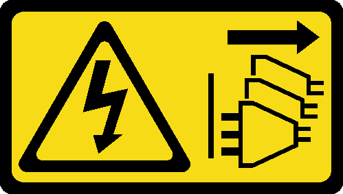
- If necessary, align and install the connector guide into the PCIe riser cage.Figure 1. Installing connector guide to riser
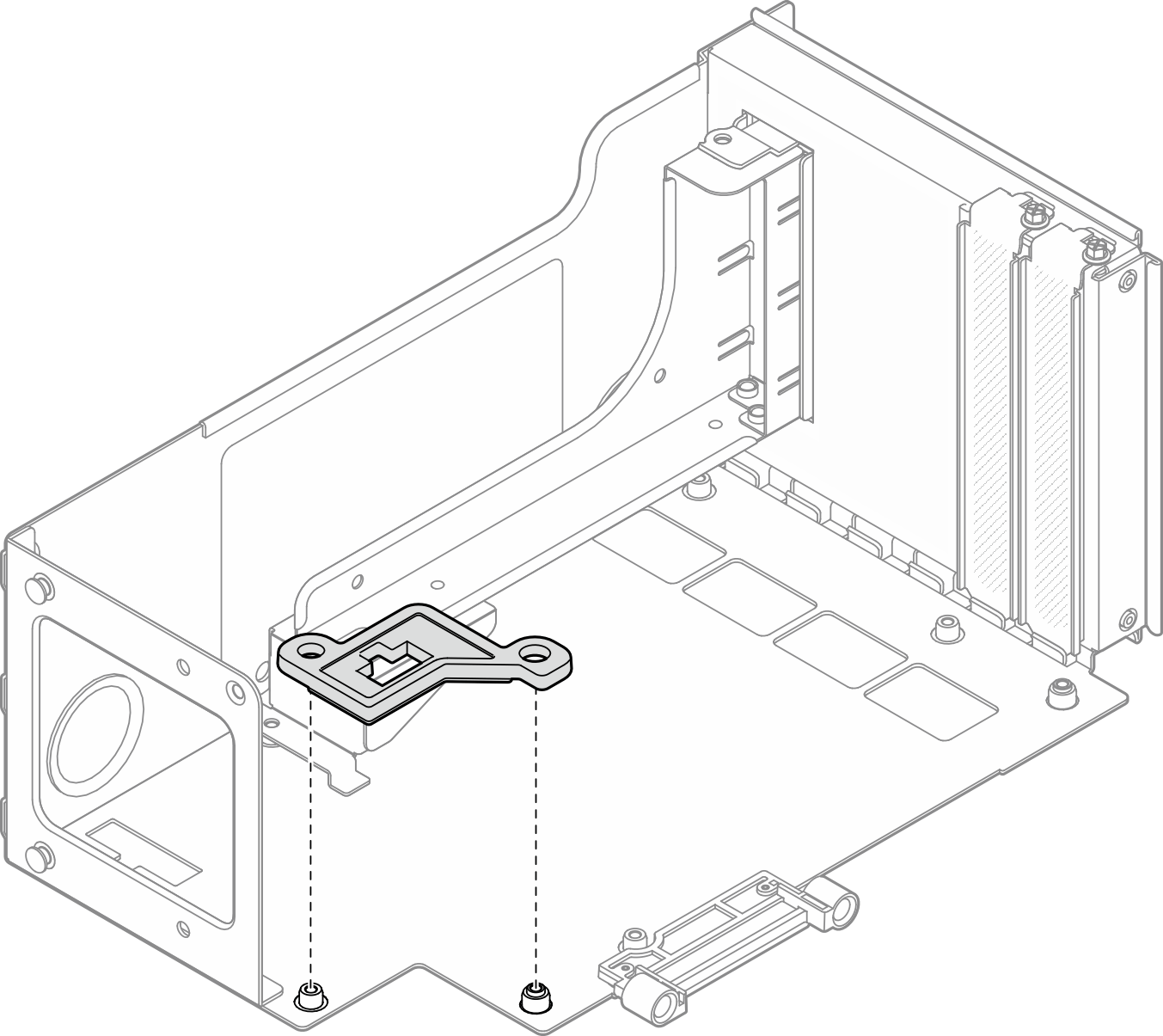
- Align the screw holes in the PCIe riser card with the screw holes in the PCIe riser cage; then, install five screws to secure the PCIe riser card.Figure 2. Installing PCIe riser card to riser
Install a PCIe riser card and cage to six slot FH riser
Procedure
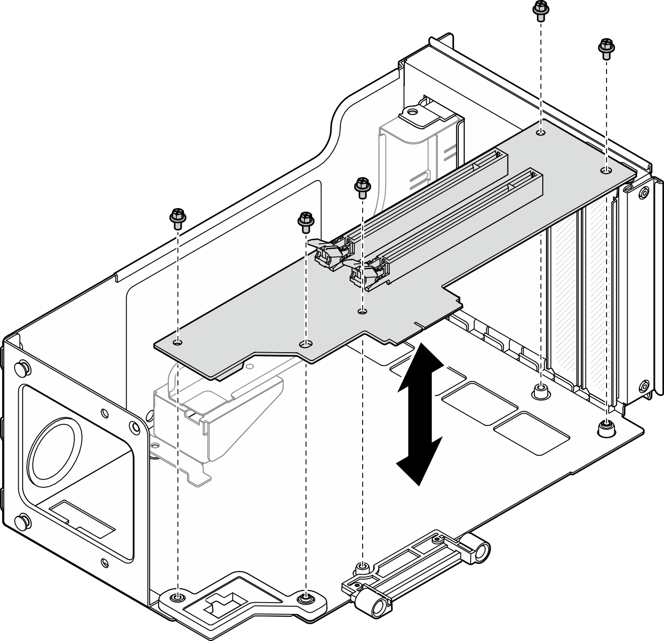
- If necessary, attach the labels onto the straight-end of the PCIe riser cables.NoteSee
PCIe riser 1 cable routing or PCIe riser 3 cable routing to identify the corresponding labels for the cables. Figure 3. PCIe riser cable
1 Straight-end of cable (connects to system board assembly) 3 Right-angle end of cable (connects to riser card) 2 Label (located near straight-end of cable) 4 Label sheet for PCIe riser cable (from labels kit) Figure 4. Attaching label onto cable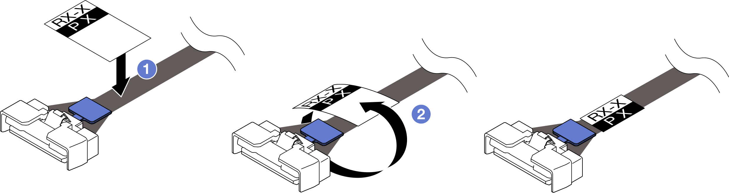
 Attach the white space portion of the label near the straight-end of the PCIe riser cable.
 Wrap the label around the cable and attach it onto the white space portion.
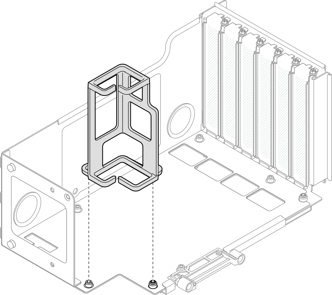
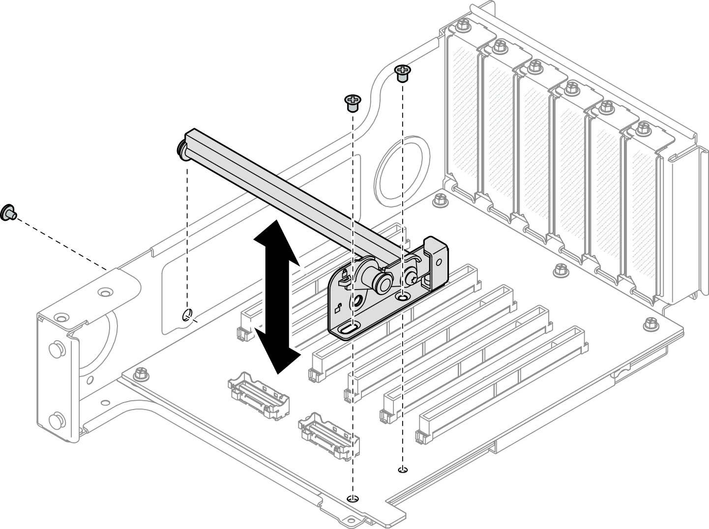
- If necessary, align and install the cable retainer into the PCIe riser cage.Figure 5. Installing cable retainer to riser
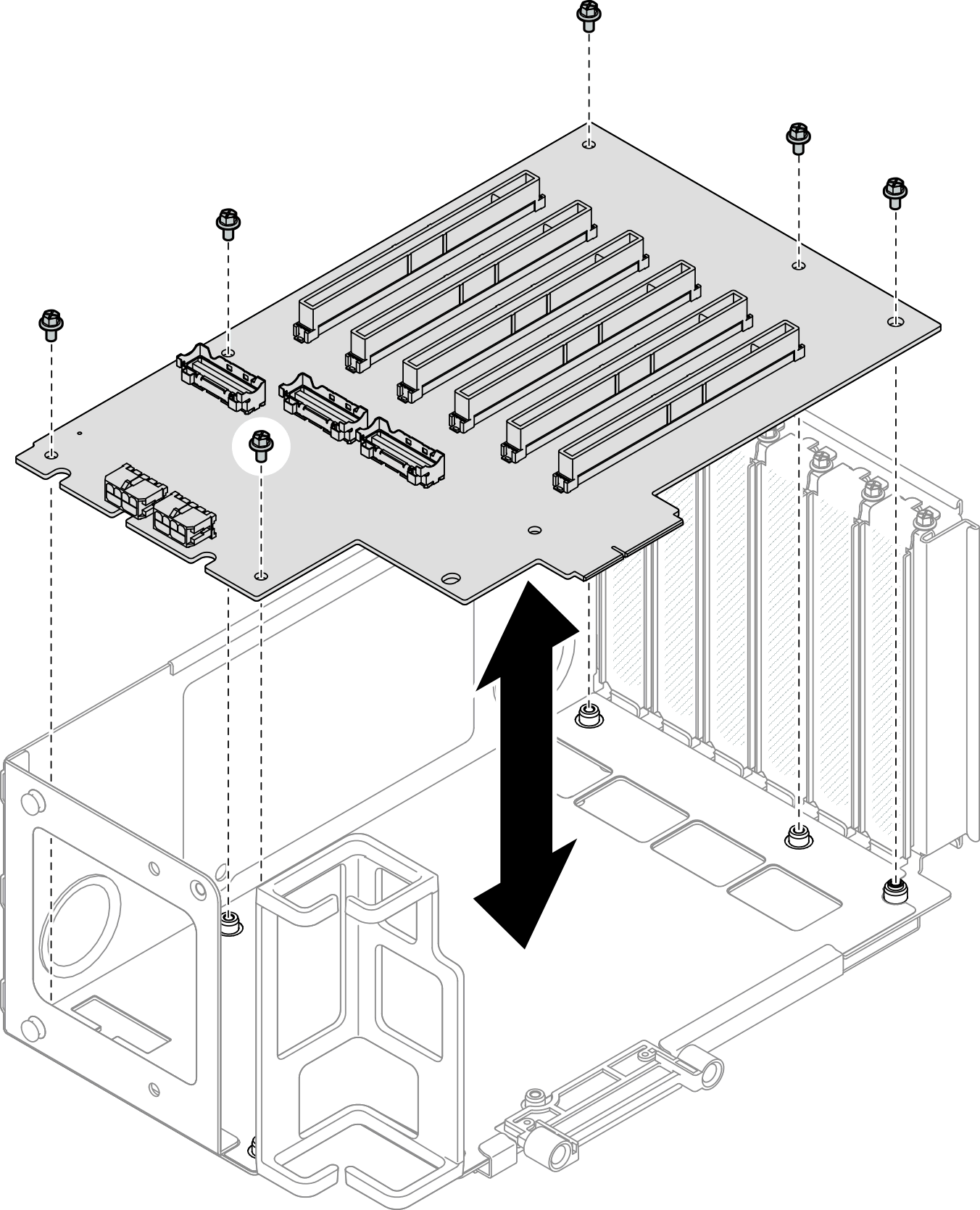
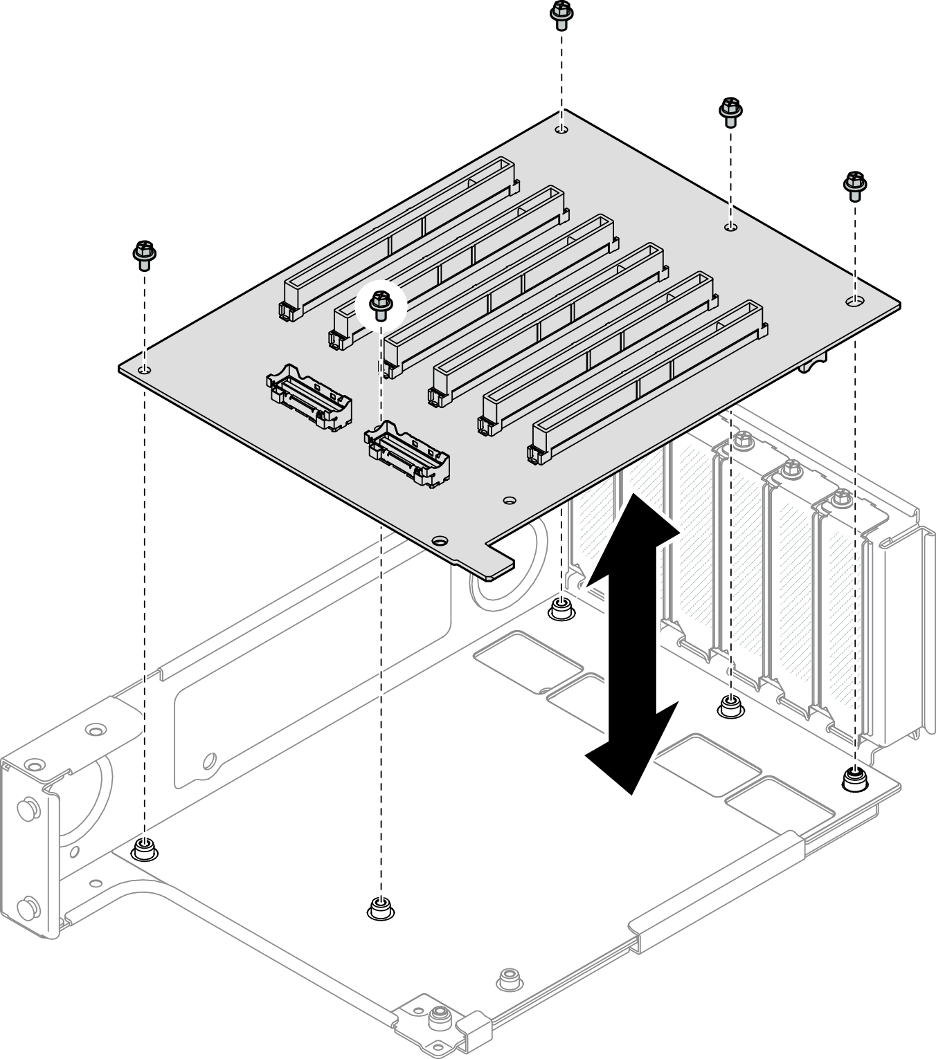
- Align the screw holes in the PCIe riser card with the screw holes in the PCIe riser cage; then, install six screws to secure the PCIe riser card.Figure 6. Installing PCIe riser card to riser
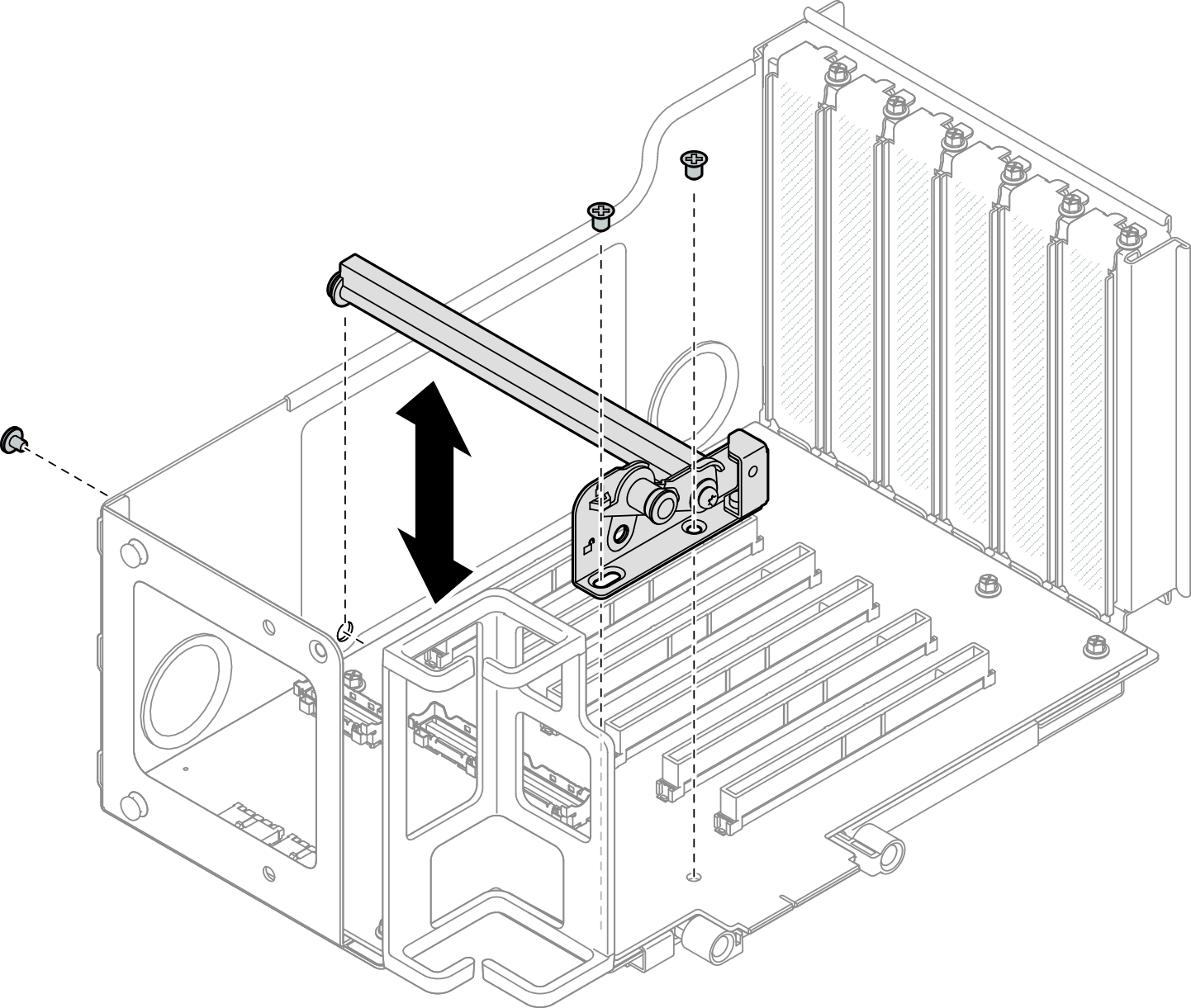
- Install the PCIe retainer into the PCIe riser cage; then, install three screws to secure the PCIe retainer.Figure 7. Installing PCIe retainer to riser
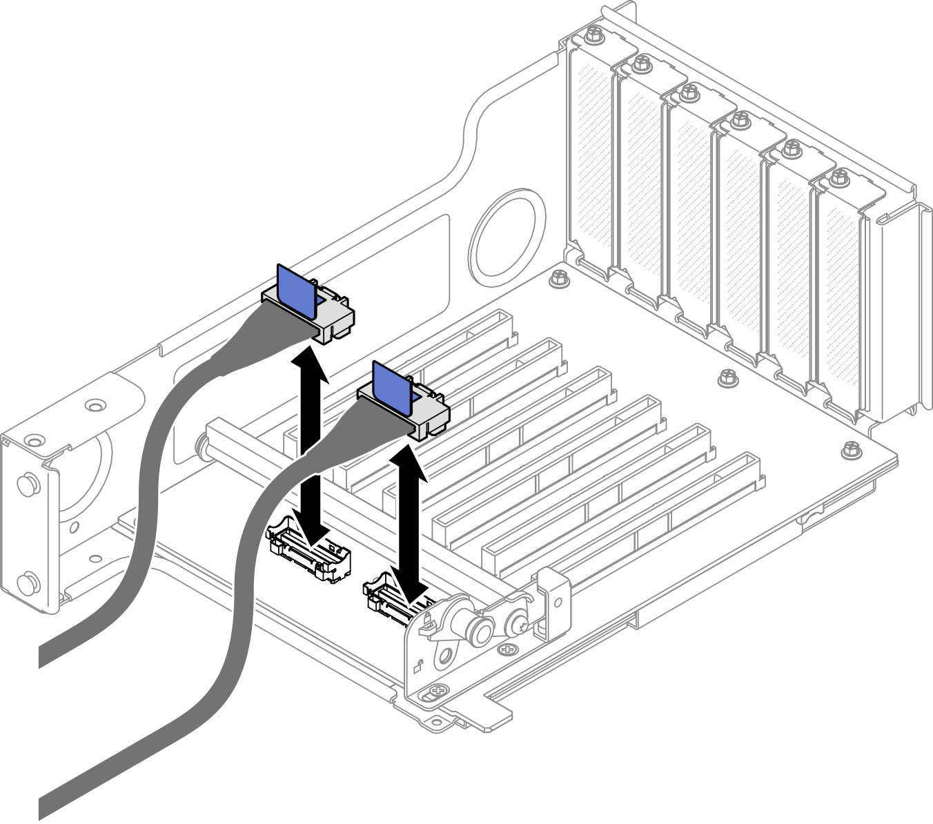
- Connect the right-angle end of the PCIe riser cables labeled R1-4, R1-5, and R1-7 (R3-4, R3-5, and R3-7) to the corresponding connectors on the inside of the PCIe riser.NoteFor a Gen 5 riser card, connect the PCIe riser cables labeled
R1-2, R1-4, and R1-7 (R3-2, R3-4, and R3-7) to the corresponding connectors. Figure 8. Connecting PCIe riser cables to inside of riser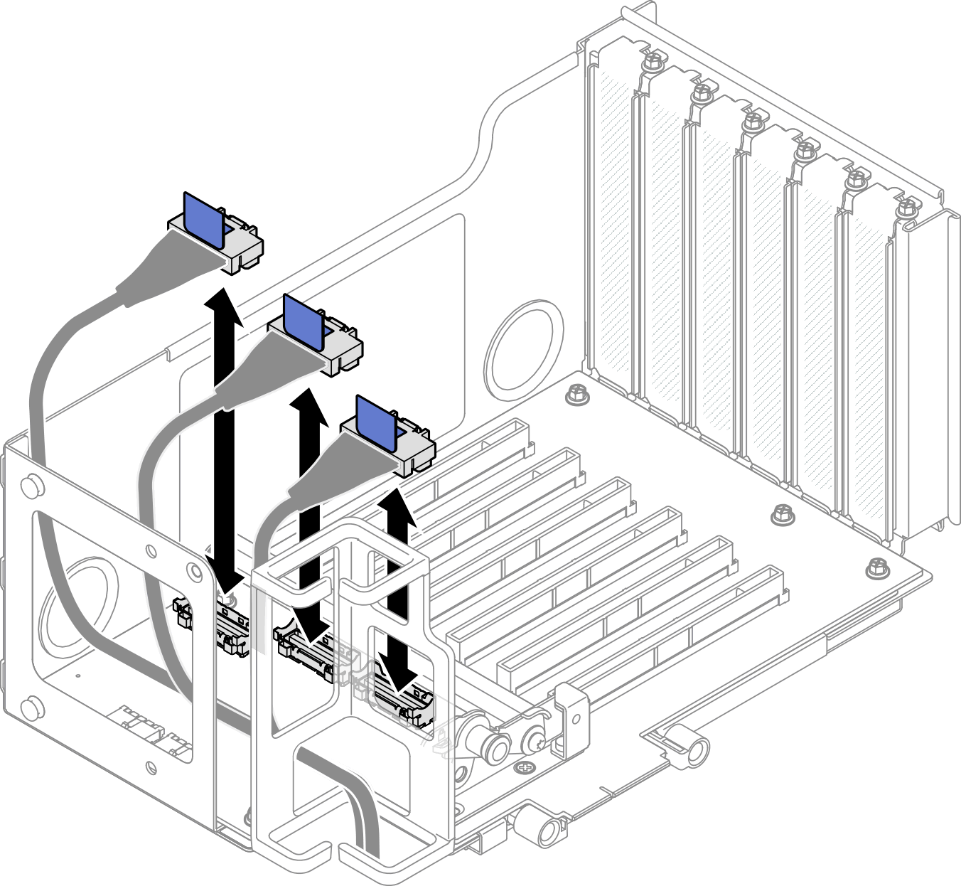
- Route the PCIe riser cables through the cable retainer as shown below.
Routing cable in PCIe riser 3 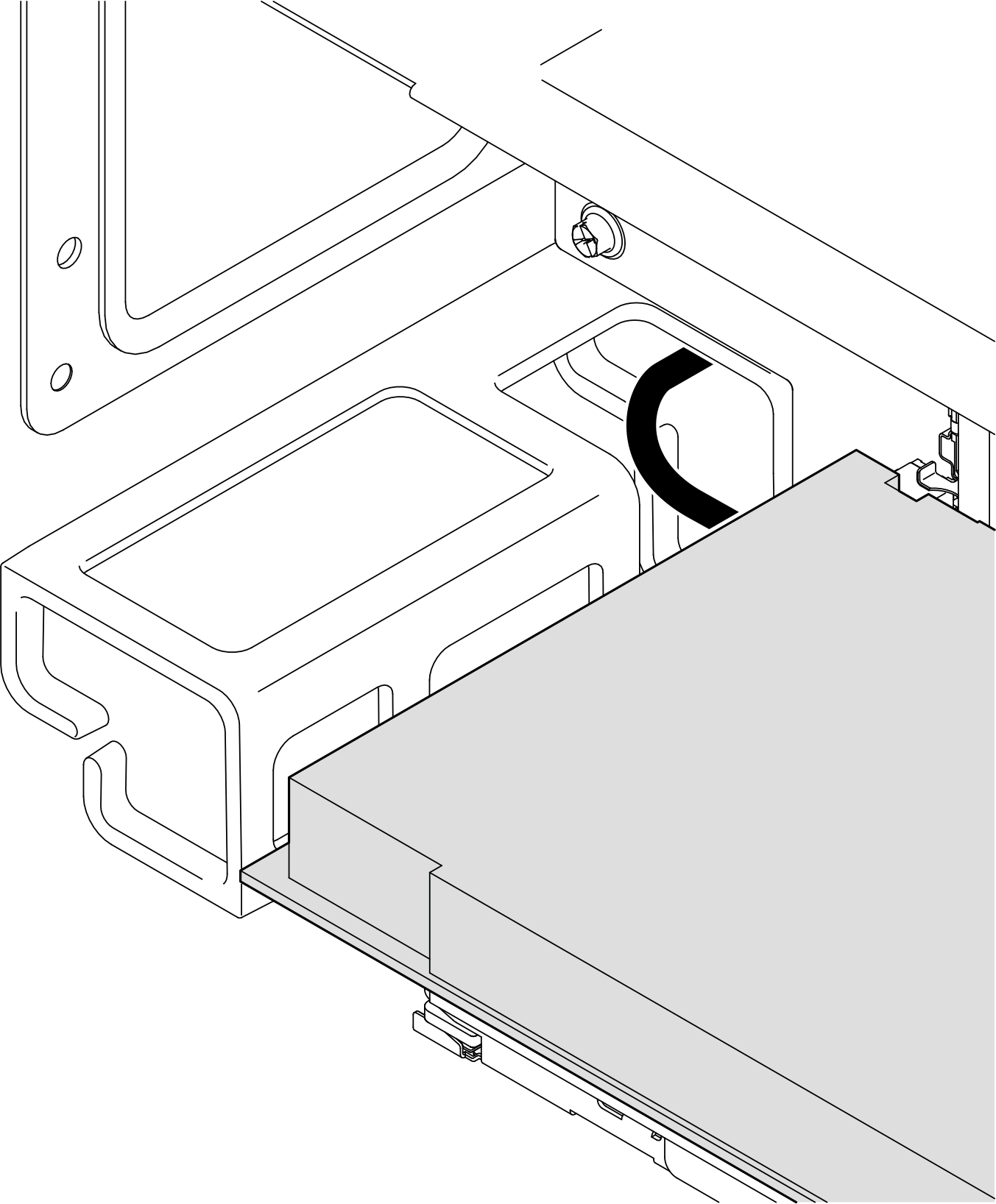
Routing cable in PCIe riser 1 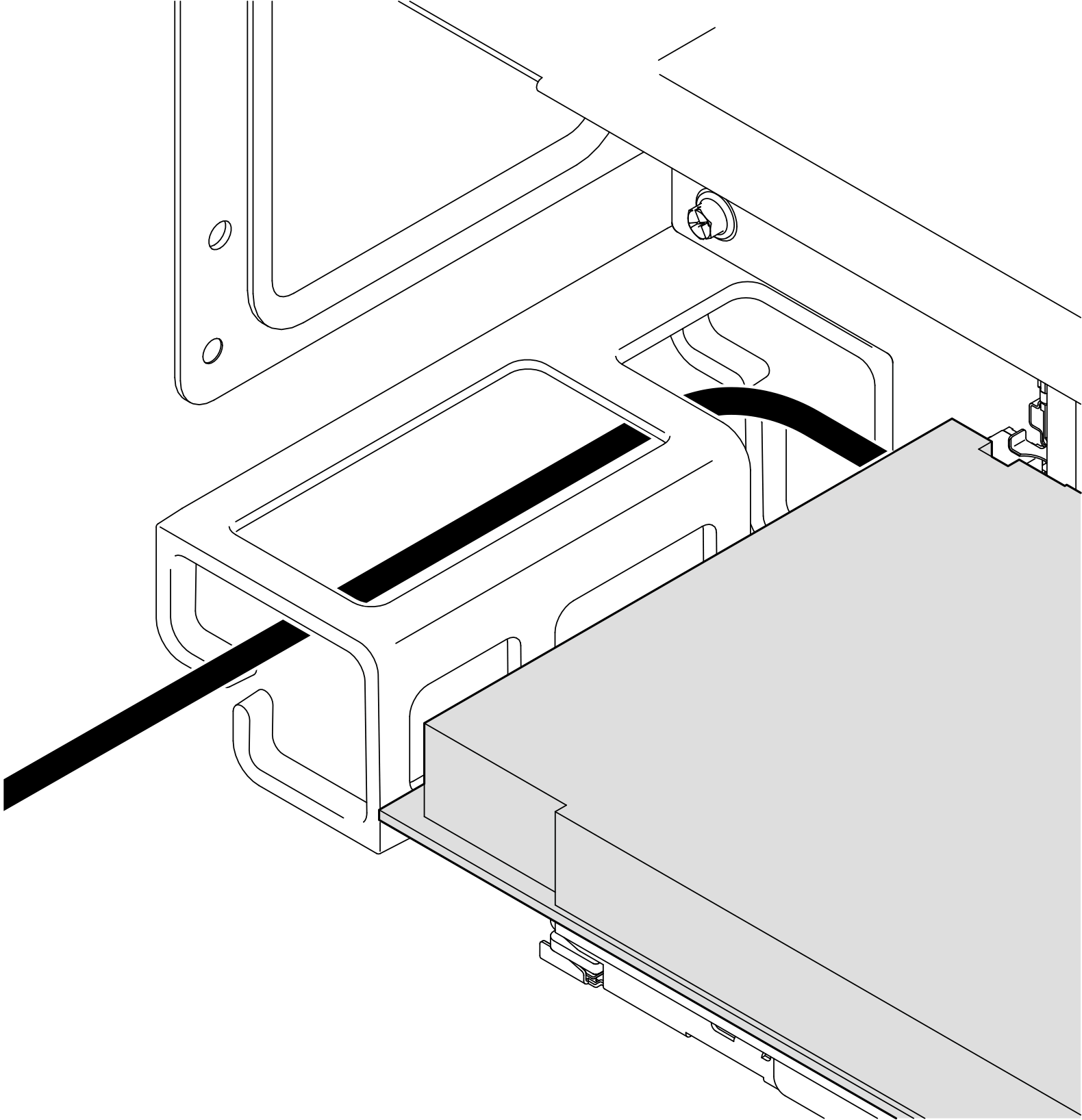
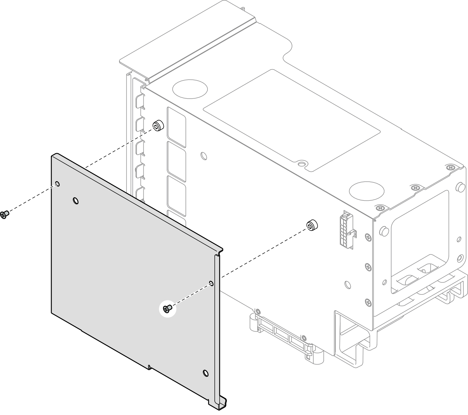
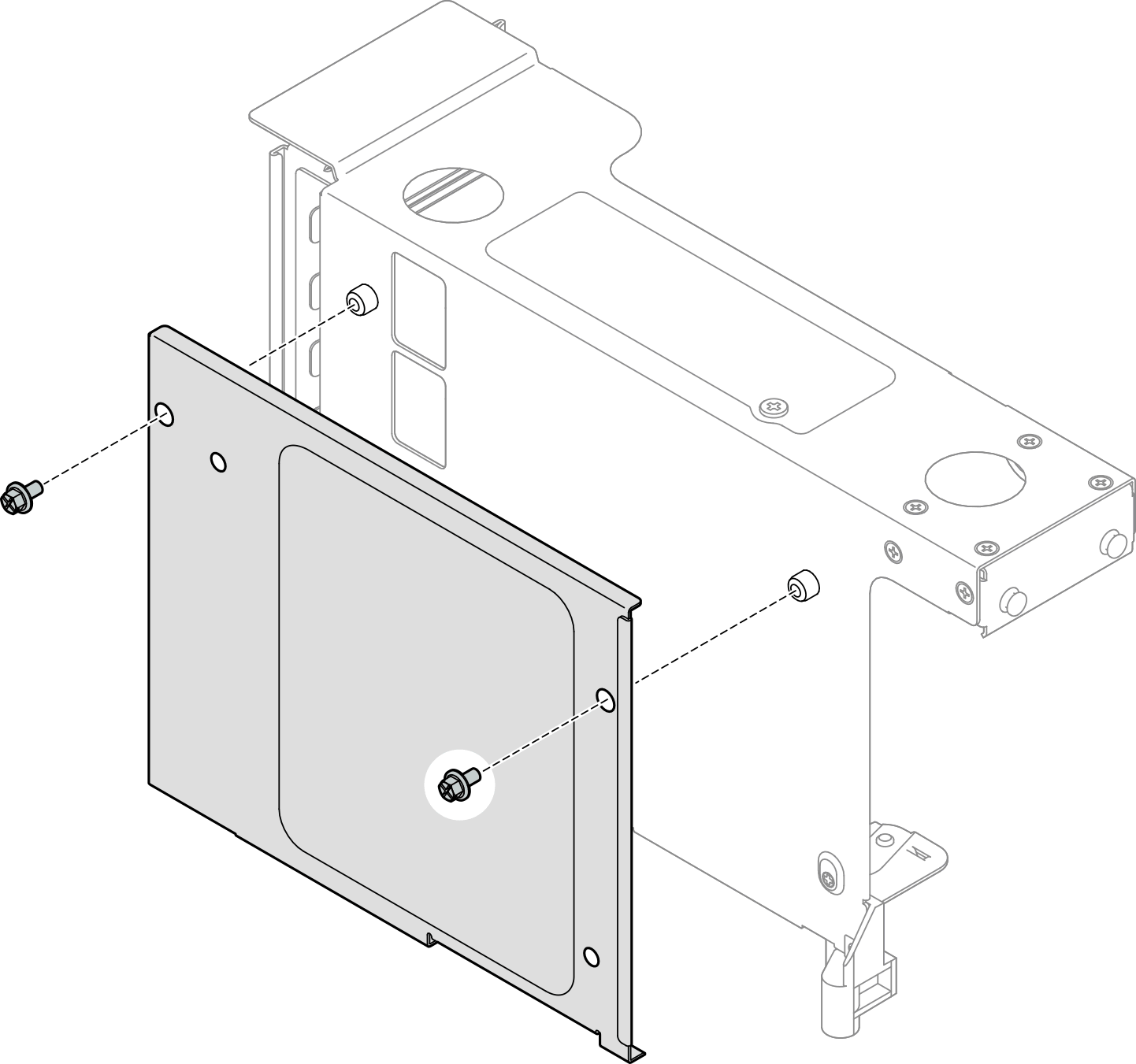
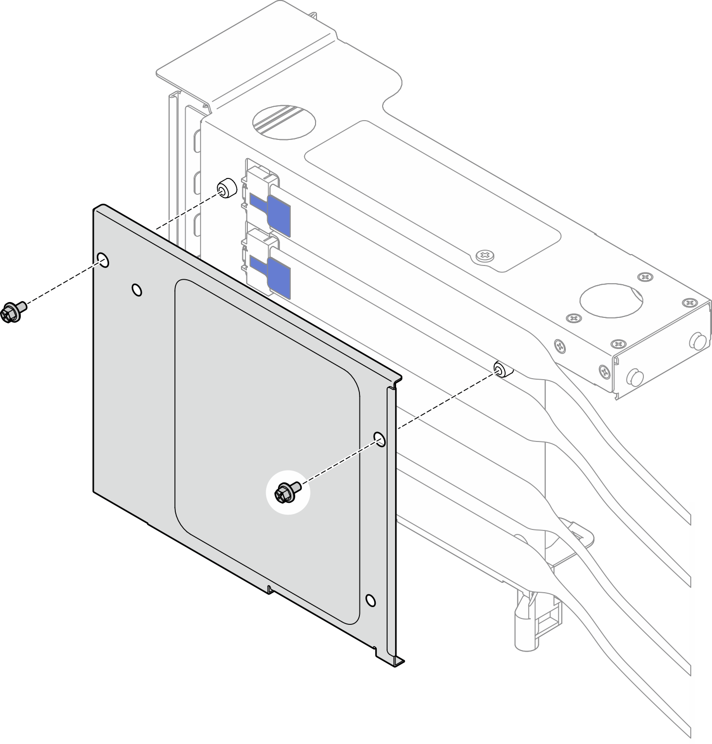
- If necessary, remove the two screws and the cover.Figure 9. Removing cover from riser
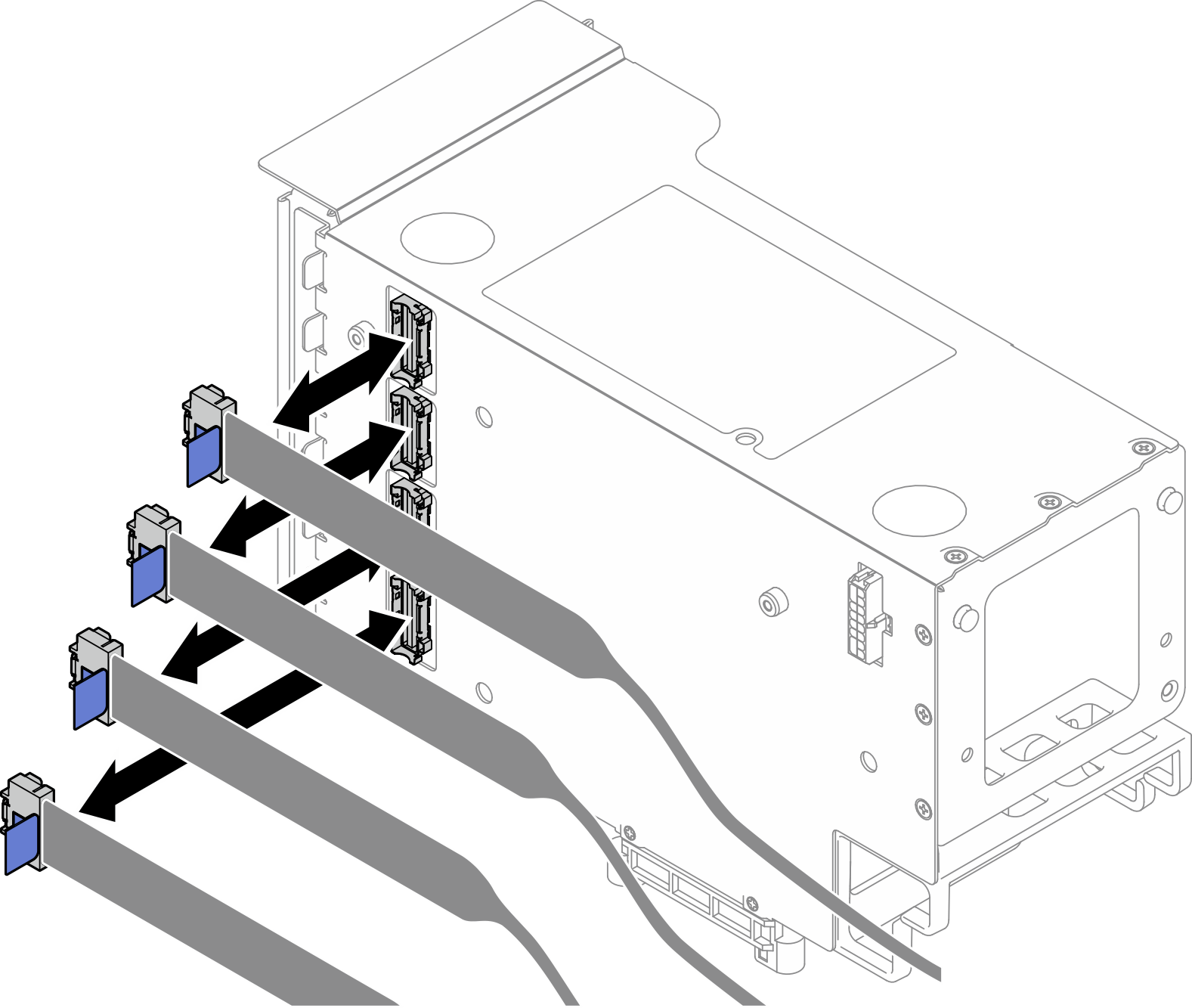
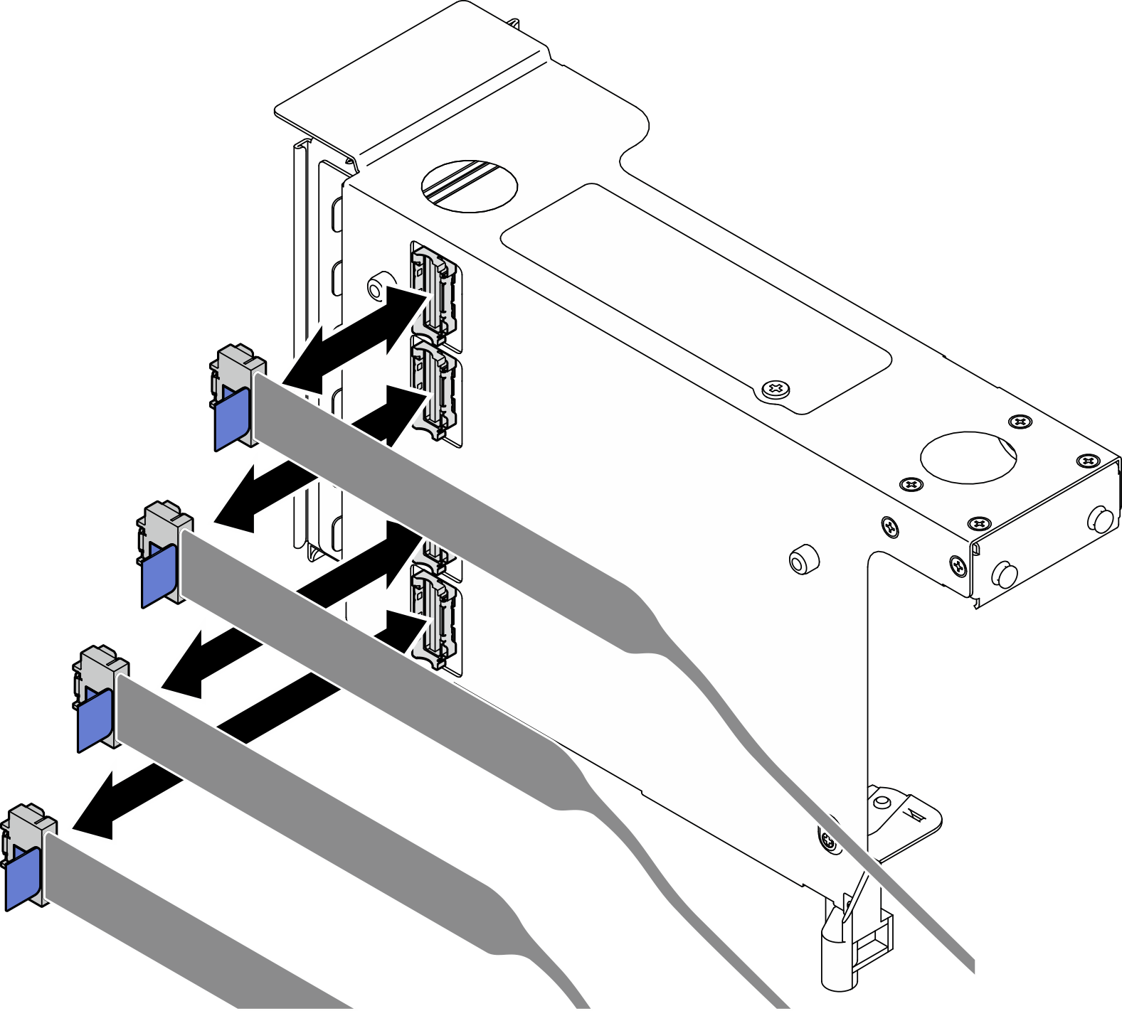
- Connect the right-angle end of the PCIe riser cables labeled R1-1, R1-3, R1-6, and R1-8 (R3-1, R3-3, R3-6, and R3-8) to the corresponding connectors on the outside of the PCIe riser.Figure 10. Connecting PCIe riser cables to outside of riser
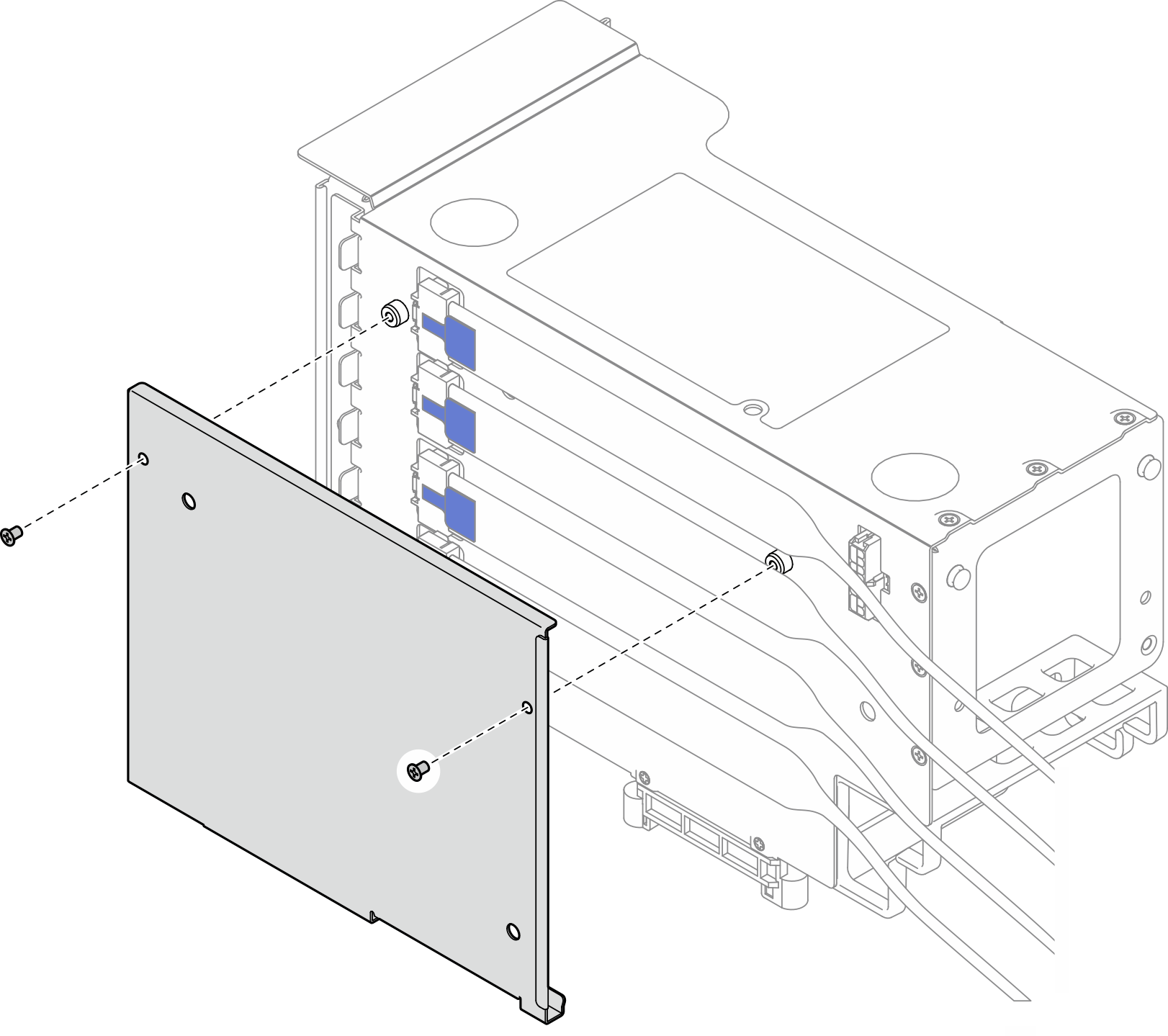
- Install the cover onto the PCIe riser cage; then, install two screws to secure the cover.Figure 11. Installing cover to riser
Install a PCIe riser card and cage to six slot HH riser
Procedure
- If necessary, attach the labels onto the straight-end of the PCIe riser cables.NoteSee
PCIe riser 2 cable routing to identify the corresponding labels for the cables. Figure 12. PCIe riser cable1 Straight-end of cable (connects to system board assembly) 3 Right-angle end of cable (connects to riser card) 2 Label (located near straight-end of cable) 4 Label sheet for PCIe riser cable (from labels kit) Figure 13. Attaching label onto cable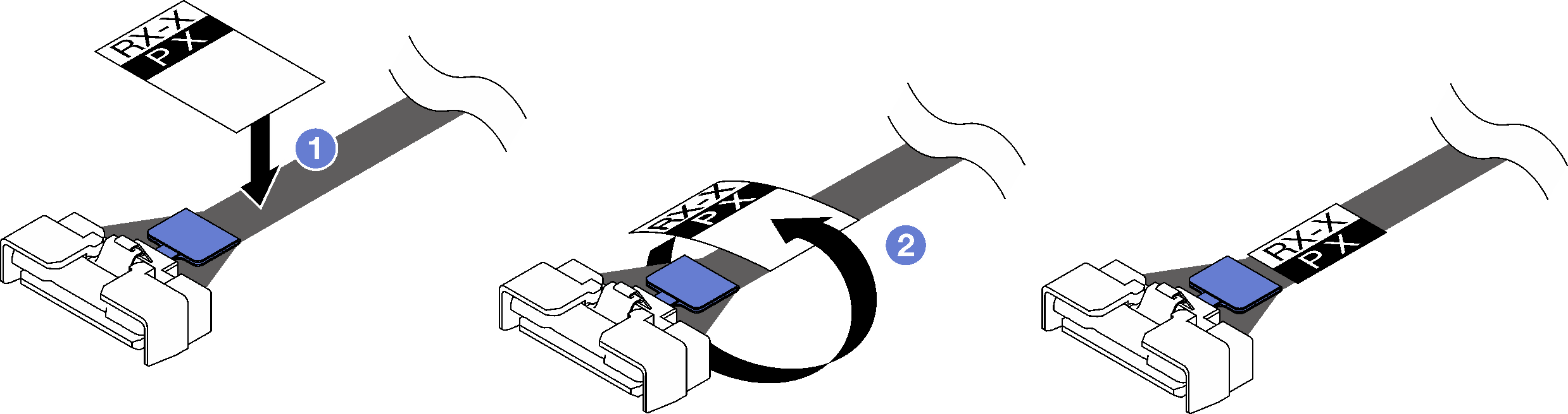
- Attach the white space portion of the label near the straight-end of the PCIe riser cable.
- Wrap the label around the cable and attach it onto the white space portion.
- Align the screw holes in the PCIe riser card with the screw holes in the PCIe riser cage; then, install five screws to secure the PCIe riser card.Figure 14. Installing PCIe riser card to riser
- Install the PCIe retainer into the PCIe riser cage; then, install three screws to secure the PCIe retainer.Figure 15. Installing PCIe retainer to riser
- Connect the right-angle end of the PCIe riser cables labeled R2-3 and R2-4 to the corresponding connectors on the inside of the PCIe riser.Figure 16. Connecting PCIe riser cables to inside of riser
- If necessary, remove the two screws and the cover.Figure 17. Removing cover from riser
- Connect the right-angle end of the PCIe riser cables labeled R2-1, R2-2, R2-5, and R2-6 to the corresponding connectors on the outside of the PCIe riser.Figure 18. Connecting PCIe riser cables to outside of riser
- Install the cover onto the PCIe riser cage; then, install two screws to secure the cover.Figure 19. Installing cover to riser
After you finish
Reinstall all the PCIe adapters. See Install a PCIe adapter.
Reinstall the 7mm drive cage. See Install the 7mm drive cage.
Reinstall the PCIe riser. See Install the PCIe riser.
Reinstall the crossbar. See Install the crossbar.
Reinstall the rear top cover. See Install the rear top cover.
Reinstall the front top cover. See Install the front top cover.
Complete the parts replacement. See Complete the parts replacement.
Demo video