Install the upper processor board (CPU BD)
Follow the instructions in this section to install the upper processor board (CPU BD).
About this task
Read Installation Guidelines and Safety inspection checklist to ensure that you work safely.
Power off the server and peripheral devices, disconnect the power cords from the primary chassis, then disconnect the power cords from the secondary chassis. See Power off the server.
Prevent exposure to static electricity, which might lead to system halt and loss of data, by keeping static-sensitive components in their static-protective packages until installation, and handling these devices with an electrostatic-discharge wrist strap or other grounding system.
If the server is installed in a rack, remove the server from the rack. See Remove the server from rails.
Go to Drivers and Software download website for ThinkSystem SR950 V3 to see the latest firmware and driver updates for your server.
Go to Update the firmware for more information on firmware updating tools.
Procedure
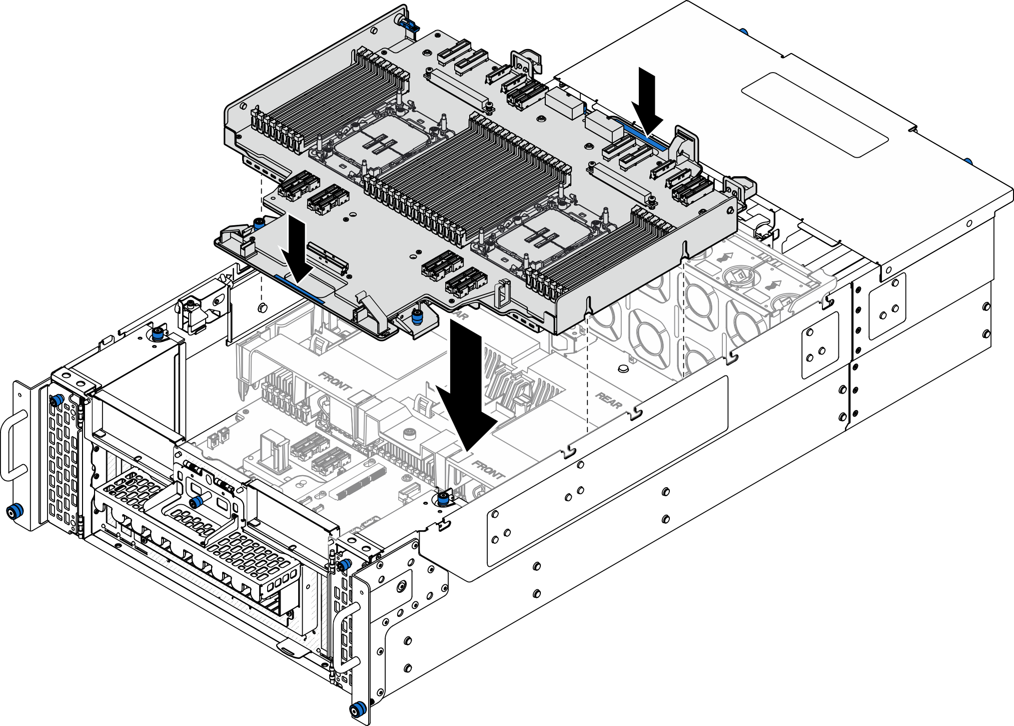
- Grasp the blue handles and lower the upper processor board (CPU BD) into the chassis until the T-pins on the inside of the chassis engages with the upper processor board (CPU BD).Figure 1. Installing upper processor board (CPU BD)
- Secure the upper processor board (CPU BD).Figure 2. Securing upper processor board (CPU BD)

 Close the plunger to the locked position.
 Tighten the three thumbscrews. Use a screwdriver if needed.
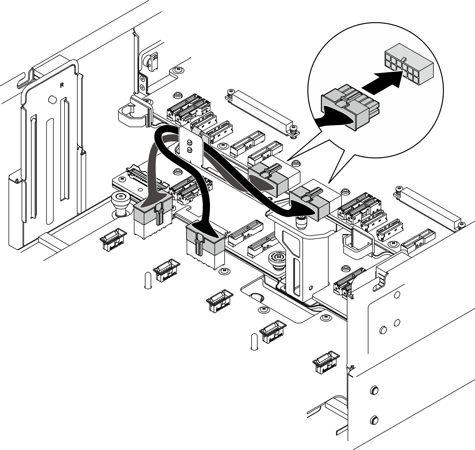
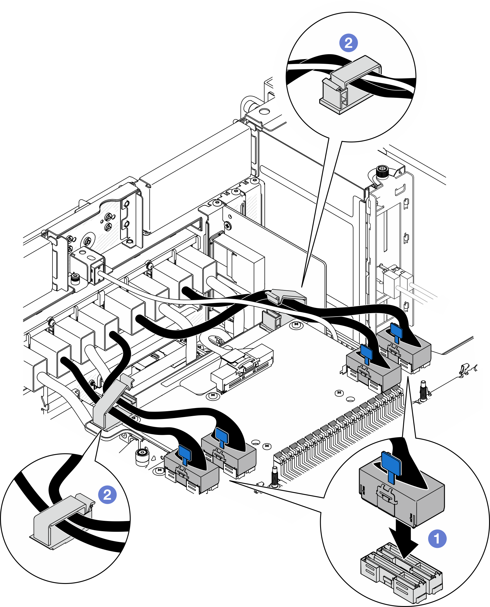
- Connect the power cables to the upper processor board (CPU BD).Figure 3. Connecting upper processor board (CPU BD) power cables
- Connect the internal UPI cables.Figure 4. Connecting internal UPI cables
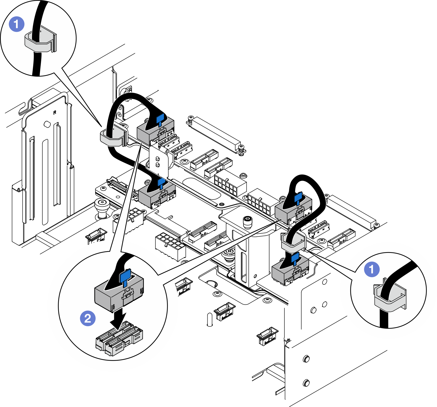
- Route the internal UPI cables through the cable clips.
- Connect the internal UPI cables to the upper processor board (CPU BD).
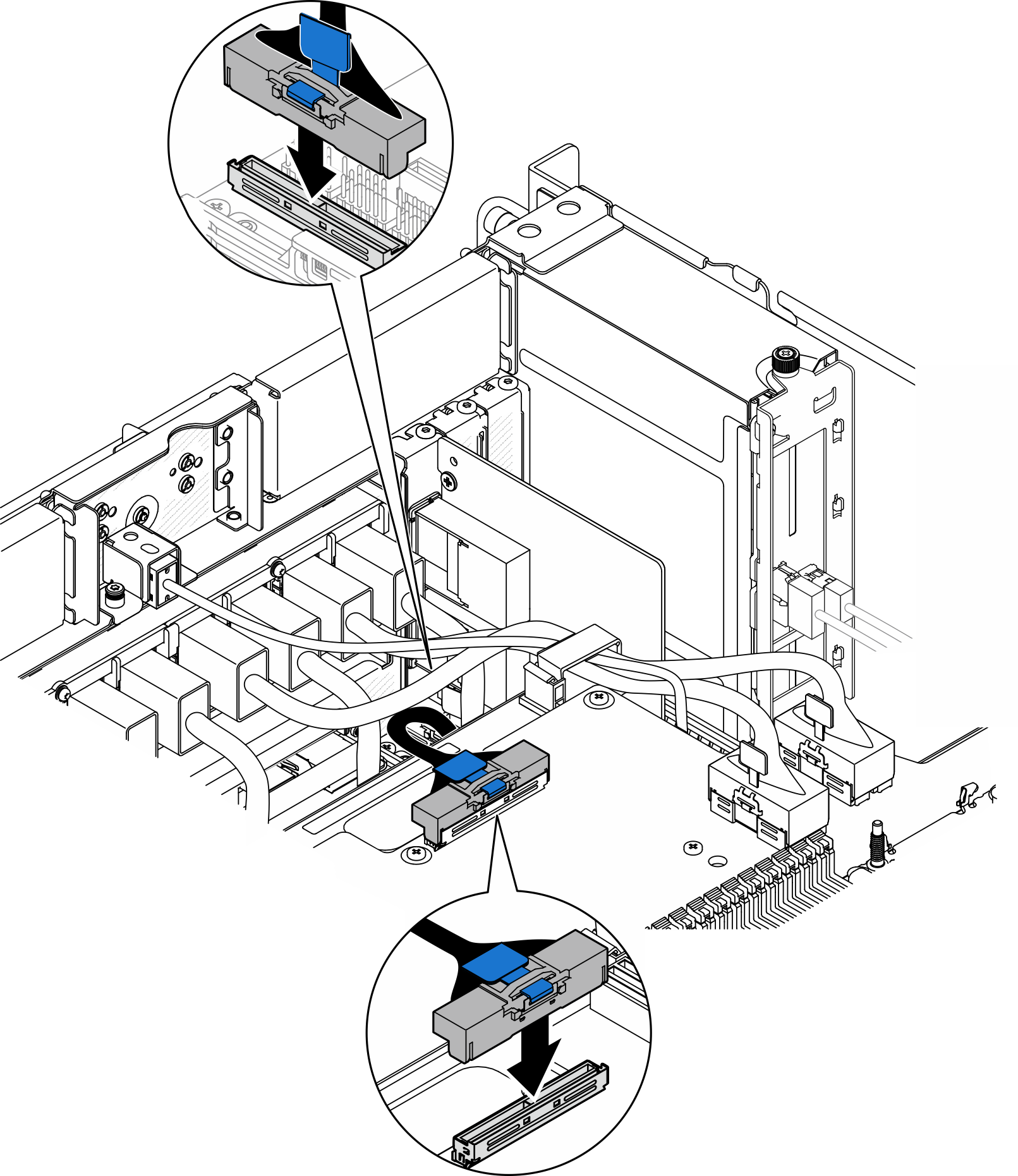
- Connect the internal sideband cable to the upper processor board (CPU BD) and lower processor board (MB).Figure 5. Connecting internal sideband cable
- Connect the UPI module cables.Figure 6. Connecting UPI module cables
- Connect the UPI module cables to the upper processor board (CPU BD).
- Route the UPI module cables through the cable clips and close them.
After you finish
If you replaced the upper processor board (CPU BD), reinstall all the memory modules and PHMs. See Install a memory module and Install a processor and heat sink.
Reinstall the upper processor board (CPU BD) air baffle. See Install the upper processor board (CPU BD) air baffle.
Reinstall the front top cover. See Install the front top cover.
Complete the parts replacement. See Complete the parts replacement.
Demo video