Install the riser for slot 10 to 15 (riser 2)
The riser for adapter slot 10 to 15 (riser 2) is in the I/O tray that is accessed from the rear of the server. After installing adapters in the riser, insert the riser in the I/O tray and secure it with two captive screws.

Install the optional M.2 backplane and optional riser bracket for slot 14 to 15 before installing the riser for adapter slot 10 through 15 (riser 2).


If you are installing an optional LOM adapter in slot 9, install it before installing the riser for slot 10 to 15 (riser 2). See Install a LOM adapter in slot 9.
Before you install the riser for slot 10 through 15 option:
If the I/O tray is installed in the server, remove it. See Remove the I/O tray.
Make sure that there is no screw (item 2 in following figure) securing the I/O tray board to the I/O tray in a location where a captive riser screw will be installed.
Make sure that there are no I/O tray fillers installed in riser slot 10 to 15.
If you are Installing the optional slot 14 to 15 bracket, make sure that it is in place. See Install a riser bracket for slot 14 to 15.
Install adapters in the riser. See Install a PCIe adapter in slot 10 to 15.
If any of the adapters in the riser have internal cables, make sure that they are connected before installing the riser in the I/O tray.
Complete the following steps to install the riser for slot 10 to 15.
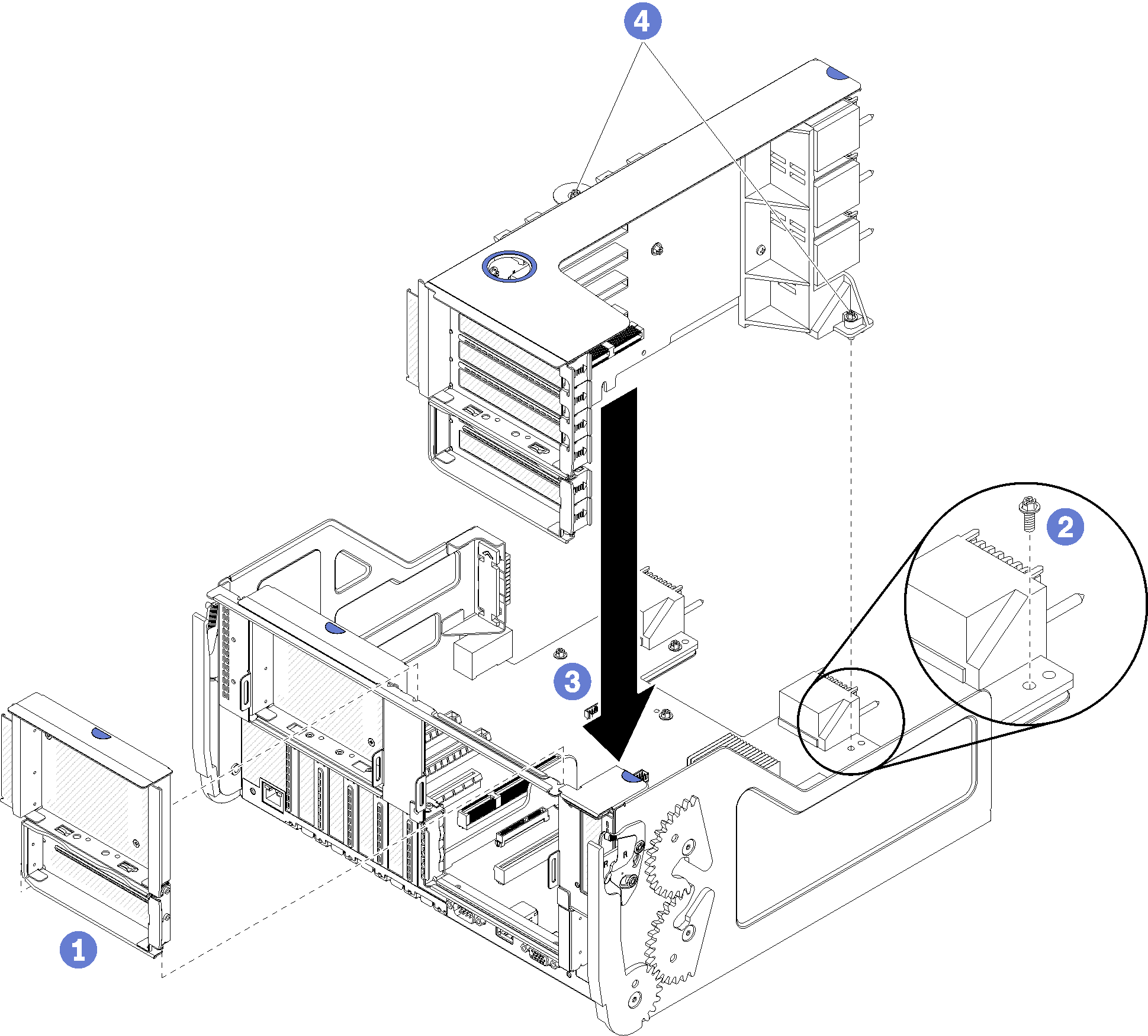
- Align the riser with the I/O tray and insert it; then, press the riser into the I/O tray until the connector is fully seated.
- Tighten the two captive screws (items 4 in preceding figure) that secure the riser to the I/O tray board.
If you have no other options to install in the I/O tray after installing the riser for slot 10 to 15, install the I/O tray in the chassis. See Install the I/O tray.
Demo video