Install the riser for slot 1 to 4 (riser 1)
The riser for adapter slot 1 to 4 (riser 1) is in the I/O tray that is accessed from the rear of the server. After installing adapters in the riser, insert the riser in the I/O tray and secure it with two captive screws.


Before you install the riser for slot 1 to 4 option:
If the I/O tray is installed in the server, remove it. See Remove the I/O tray.
Make sure that there is no screw (item 2 in following figure) securing the I/O tray board to the I/O tray in a location where a captive riser screw will be installed.
Make sure that there are no I/O tray fillers installed in riser slot 1 to 4.
Install adapters in the riser. See Install a PCIe adapter in slot 1 to 4.
If any of the adapters in the riser have internal cables, make sure that they are connected before installing the riser in the I/O tray.
Complete the following steps to install the riser for slot 1 to 4.
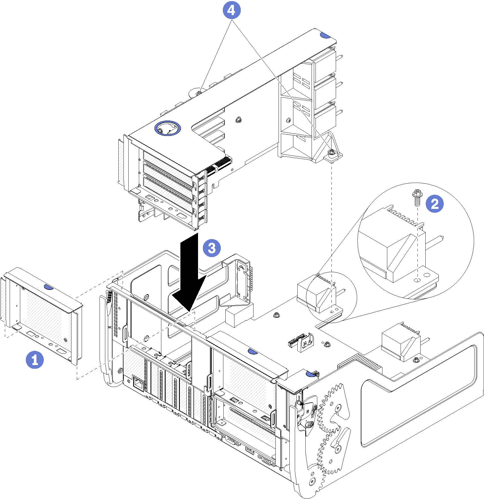
- Align the riser with the I/O tray and insert it; then, press the riser into the I/O tray until the connector is fully seated.
- Tighten the two captive screws (items 4 in preceding figure) that secure the riser to the I/O tray board.
If you have no other options to install in the I/O tray after installing the riser for slot 1 to 4, install the I/O tray in the chassis. See Install the I/O tray.
Demo video