Remove the firmware and RoT security module
Follow instructions in this section to remove the ThinkSystem V3 Firmware and Root of Trust Security Module (firmware and RoT security module).
About this task
This task must be operated by trained technicians that are certified by Lenovo Service. Do not attempt to remove or install the part without proper training and qualification.
Read Installation Guidelines and Safety inspection checklist to ensure that you work safely.
Power off the server and peripheral devices and disconnect the power cords and all external cables. See Power off the server.
Prevent exposure to static electricity, which might lead to system halt and loss of data, by keeping static-sensitive components in their static-protective packages until installation, and handling these devices with an electrostatic-discharge wrist strap or other grounding system.
After replacing the firmware and RoT security module, update the firmware to the specific version supported by the server. Make sure that you have the required firmware or a copy of the pre-existing firmware before you proceed.
If the server is installed in a rack, slide the server out on its rack slide rails to gain access to the top cover, or remove the server from the rack. See Remove the server from rack.
Procedure
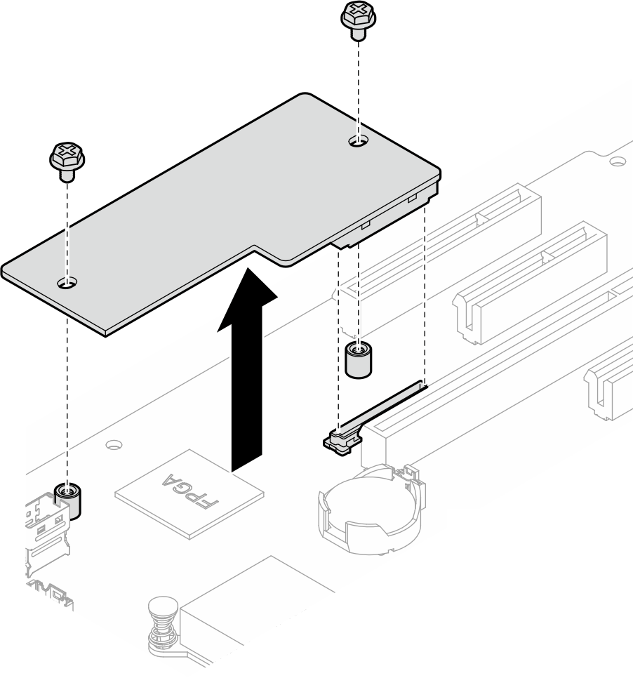
- Remove the two screws that secure the Firmware and RoT security module to the system board, and remove the module.Figure 1. Firmware and RoT security module removal
After you finish
Install a replacement unit. See Install the firmware and RoT security module
If you are instructed to return the component or optional device, follow all packaging instructions, and use any packaging materials for shipping that are supplied to you.
Demo video