Remove the system board
Follow instructions in this section to remove the system board.
About this task
- S002
 CAUTIONThe power-control button on the device and the power switch on the power supply do not turn off the electrical current supplied to the device. The device also might have more than one power cord. To remove all electrical current from the device, ensure that all power cords are disconnected from the power source.
 - S012
 CAUTIONHot surface nearby.
 - S017
 CAUTIONHazardous moving fan blades nearby. Keep fingers and other body parts away.
Read Installation Guidelines and Safety inspection checklist to ensure that you work safely.
Power off the server and peripheral devices and disconnect the power cords and all external cables. See Power off the server.
If the server is installed in a rack, remove the server from the rack.
Remove any locking device that secures the server cover, such as a Kensington lock or a pad lock.
Procedure
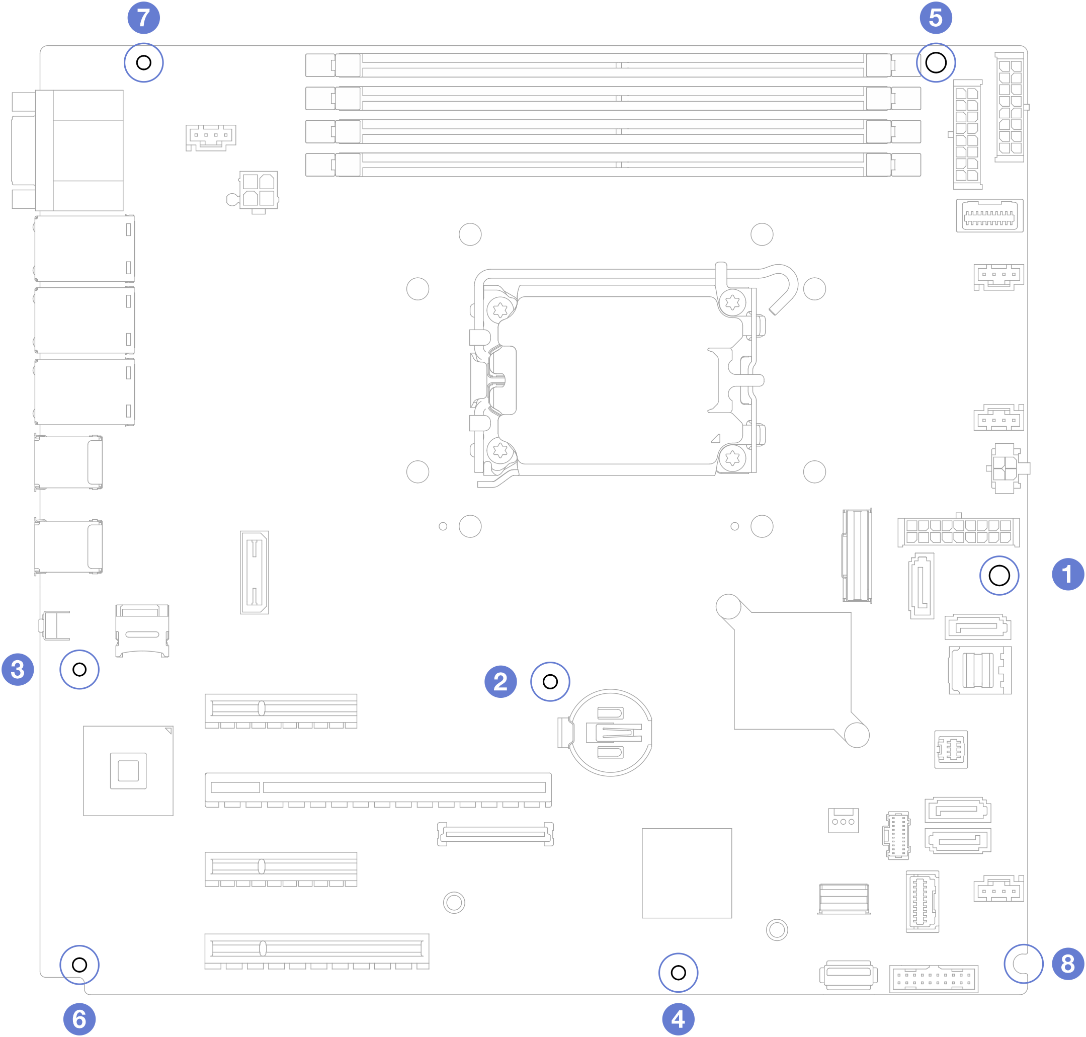
- Remove the eight screws that secure the system board following the recommended numerical sequence shown in the illustration; then, carefully remove the system board out of the chassis.NoteFor reference, the torque required to fully loosen the screws is 0.5–0.6 newton-meters, 4.5–5.5 inch-pounds.Figure 1. Removing the screws that secure the system board.
After you finish
If you are instructed to return the component or optional device, follow all packaging instructions, and use any packaging materials for shipping that are supplied to you.
ImportantBefore you return the system board, make sure that you install the processor socket dust covers from the new system board. To replace a processor socket dust cover:Take a dust cover from the processor socket assembly on the new system board and orient it correctly above the processor socket assembly on the removed system board.
Gently press down the dust cover legs to the processor socket assembly, pressing on the edges to avoid damage to the socket pins. You might hear a click on the dust cover is securely attached.
Make sure that the dust cover is securely attached to the processor socket assembly.
Demo video