Install the system board
Follow instructions in this section to install the system board.
About this task
- S002
 CAUTIONThe power-control button on the device and the power switch on the power supply do not turn off the electrical current supplied to the device. The device also might have more than one power cord. To remove all electrical current from the device, ensure that all power cords are disconnected from the power source.
 - S012
 CAUTIONHot surface nearby.
 - S017
 CAUTIONHazardous moving fan blades nearby. Keep fingers and other body parts away.
Read Installation Guidelines and Safety inspection checklist to ensure that you work safely.
Touch the static-protective package that contains the component to any unpainted metal surface on the server; then, remove it from the package and place it on a static-protective surface.
Go to Drivers and Software download website for ThinkSystem ST250 V3 to see the latest firmware and driver updates for your server.
Go to Update the firmware for more information on firmware updating tools.
Procedure
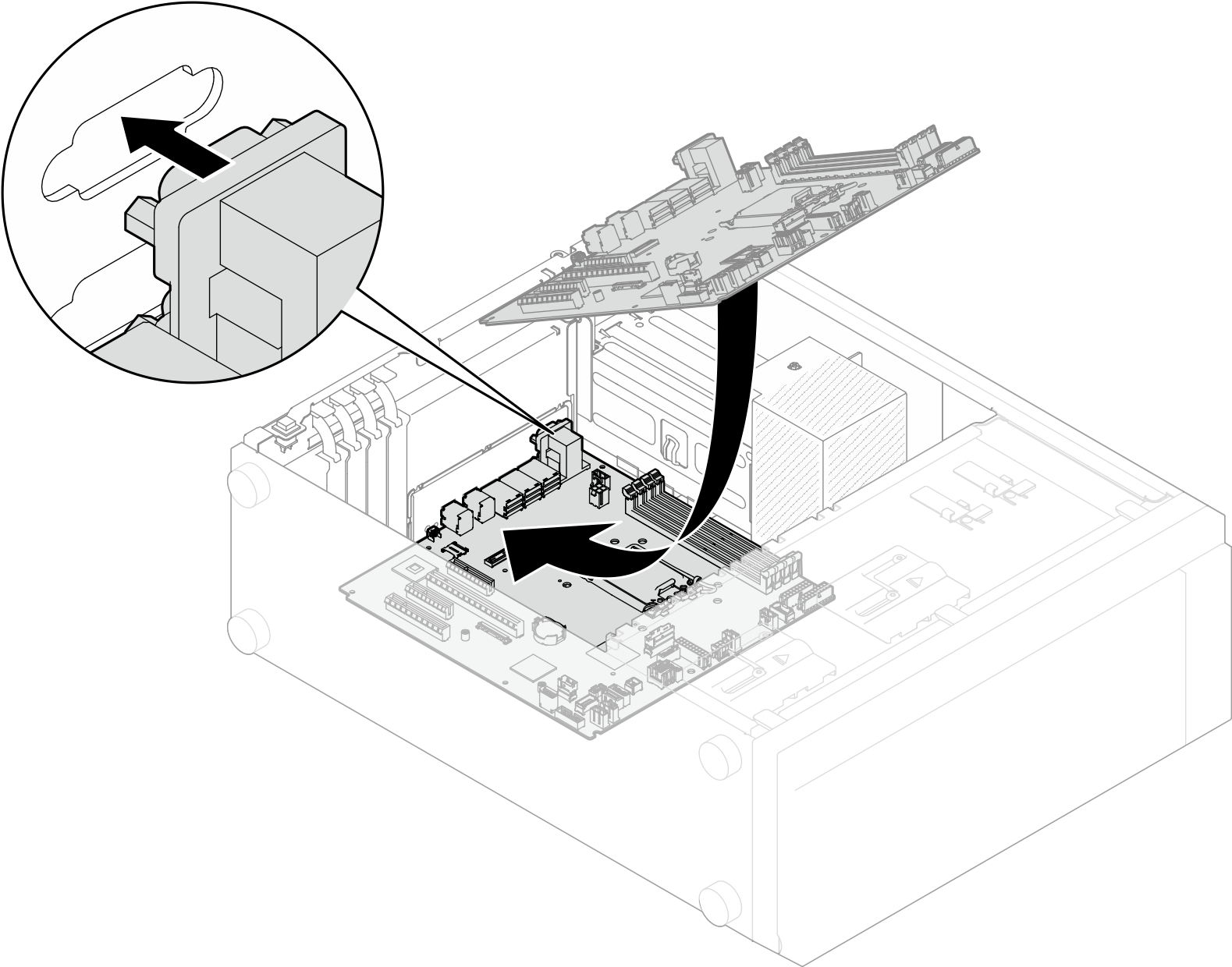
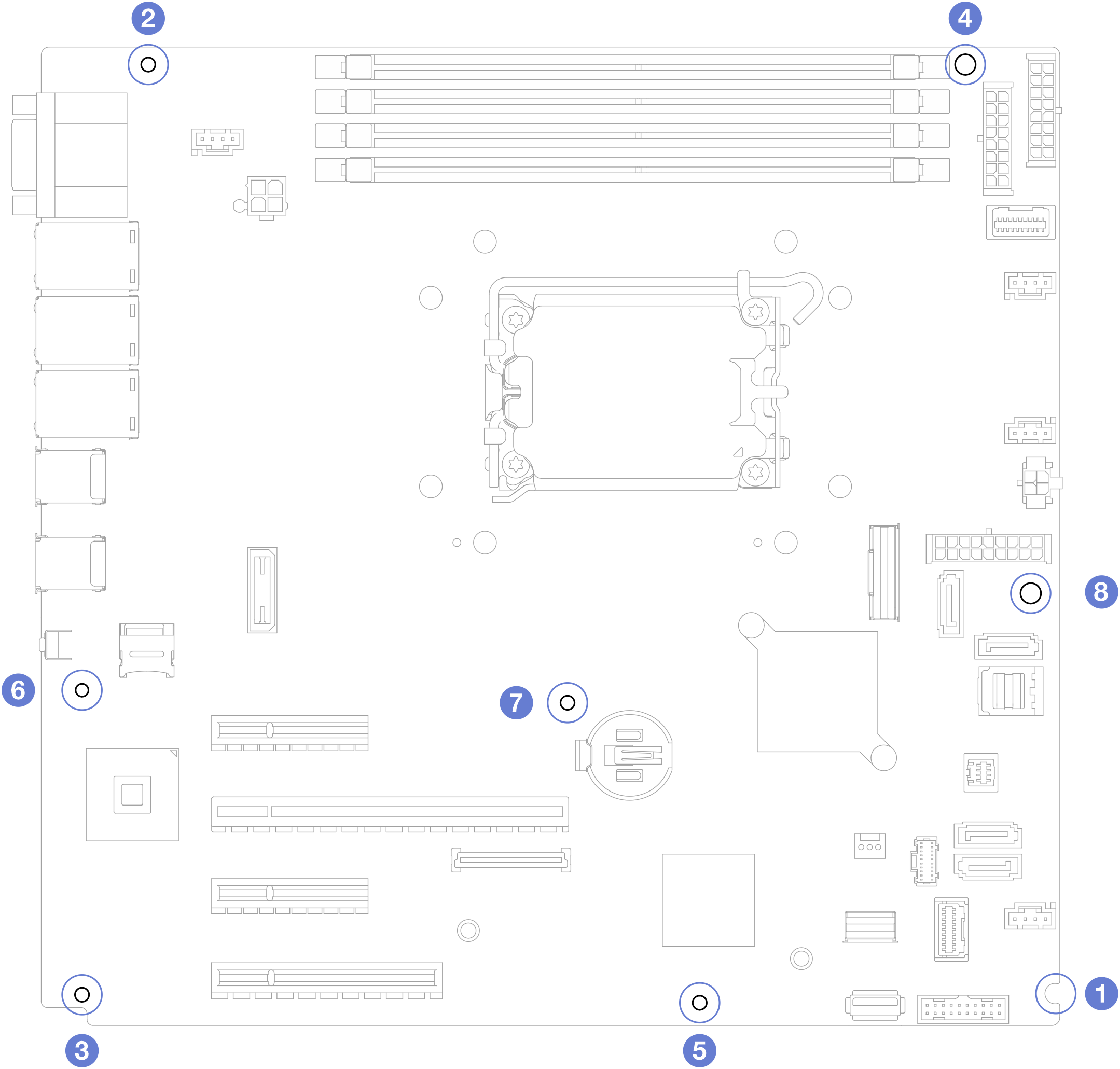
- Note the orientation of the new system board, and carefully place it into the chassis. Ensure that the serial port on the system board is inserted into the corresponding slot, and the eight screw holes on the system board are aligned with the corresponding mounting studs on the chassis.Figure 1. Installing the system board
- Secure the system board by tightening the eight screws in the sequence shown in the illustration.NoteFor reference, the torque required to fully tighten the screws is 0.5-0.6 newton-meters, 4.5-5.5 inch-pounds.Figure 2. Tightening the screws to secure the system board
After you finish
Reconnect all the required cables to the same connectors on the system board as the defective system board. See Internal cable routing.
Reinstall the Firmware and RoT security module. See Install the firmware and RoT security module.
Reinstall the processor. See Install the processor.
Reinstall the heat sink and fan assembly. See Install the heat sink and the fan module.
Reinstall the memory module. See Install a memory module.
Reinstall the PCIe adapter. See Install the PCIe adapter.
Reinstall the M.2 adapter. See Install the M.2 boot adapter.
Reinstall the rear system fan. See Install the rear system fan.
Ensure that all components have been reassembled correctly and that no tools or loose screws are left inside the server.
Reinstall the server cover. See Install the server cover.
If the sever was installed in a rack, reinstall the server into the rack. See Install the server to rack.
Reconnect the power cords and any cables that you removed.
Power on the server and any peripheral devices. See Power on the server.
Update the vital product data (VPD). See Update the Vital Product Data (VPD).
Machine type number and serial number can be found on the ID label, see Identify the server and access the Lenovo XClarity Controller.
If hiding TPM or updating TPM firmware is needed, see Hide/observe TPM or Update the TPM firmware.
Optionally, enable UEFI Secure Boot. See Enable UEFI Secure Boot.
Demo video