Install the server to the rack
Follow the instructions in this section to install the tower-to-rack conversion kit to the server, if necessary, and then the server to the rails on the rack.
About this task
Read Installation Guidelines and Safety inspection checklist to ensure that you work safely.
Power off the server and disconnect all power cords for this task. See Power off the server.
Prevent exposure to static electricity, which might lead to system halt and loss of data, by keeping static-sensitive components in their static-protective packages until installation, and handling these devices with an electrostatic-discharge wrist strap or other grounding system.
Procedure
- If necessary, install the tower-to-rack conversion kit, including the EIA brackets and the rail and latch covers.NoteFor tower server installation, the edges on the rails or the friction caused by the installation might scratch or damage the chassis coating. Applying rail and latch covers can help reduce scratching when installing the server into a rack.
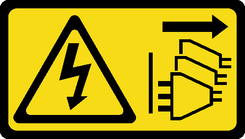
- Align the holes in the right EIA bracket with the corresponding holes on the top of the chassis; then, install the three screws to secure the right EIA bracketFigure 1. Installation of the right EIA bracket
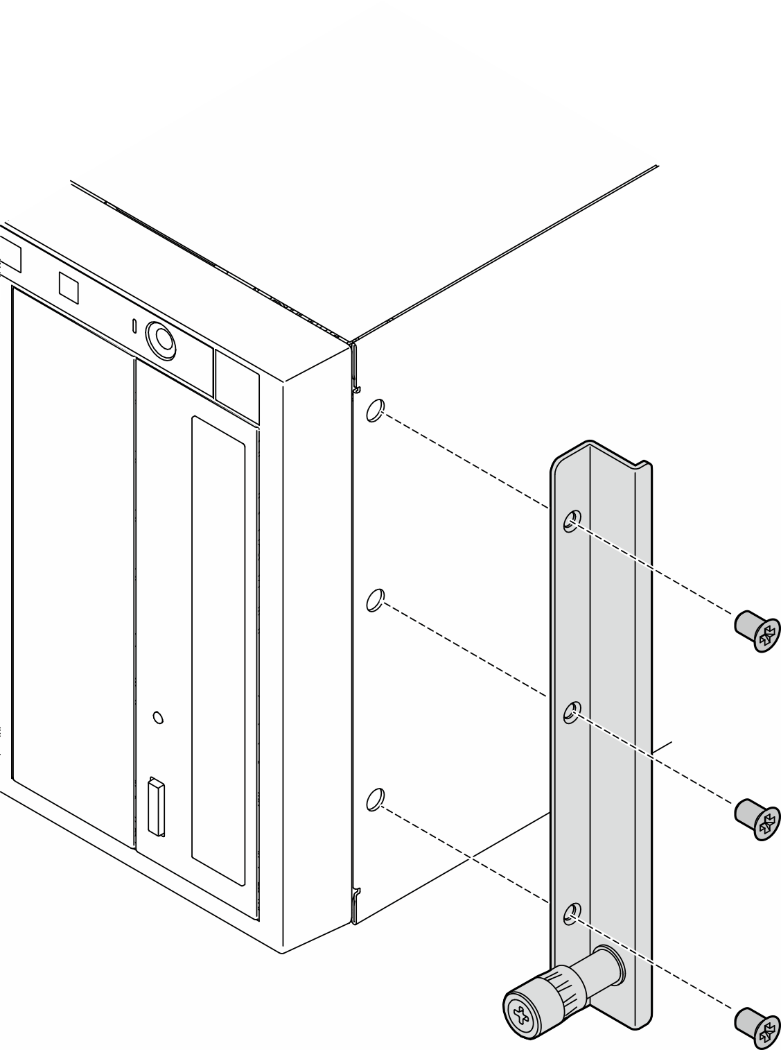
- Align the holes in the left EIA bracket with the corresponding holes on the bottom of the chassis; then, install the three screws to secure the left EIA bracket.Figure 2. Installation of the left EIA bracket
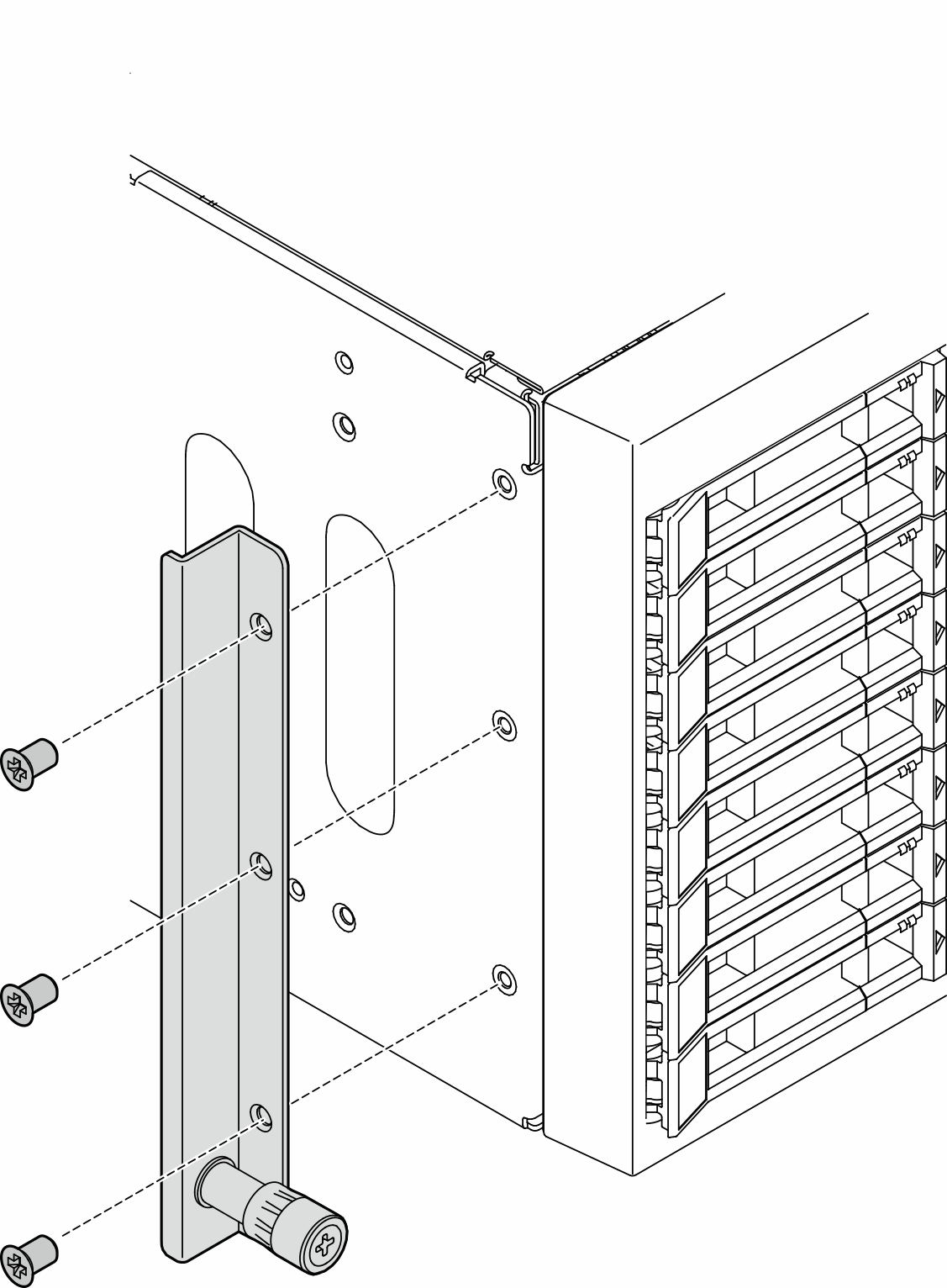
- Peel off the wrapping plastic and apply the left latch cover to the front latch of the left rail.Figure 3. Applying the left latch cover
- Peel off the wrapping plastic and apply one rail cover strip to the bottom surface of the left rail.Figure 4. Applying the left rail cover strip
- Align the holes in the right EIA bracket with the corresponding holes on the top of the chassis; then, install the three screws to secure the right EIA bracket
- If necessary, install the rails to the rack.
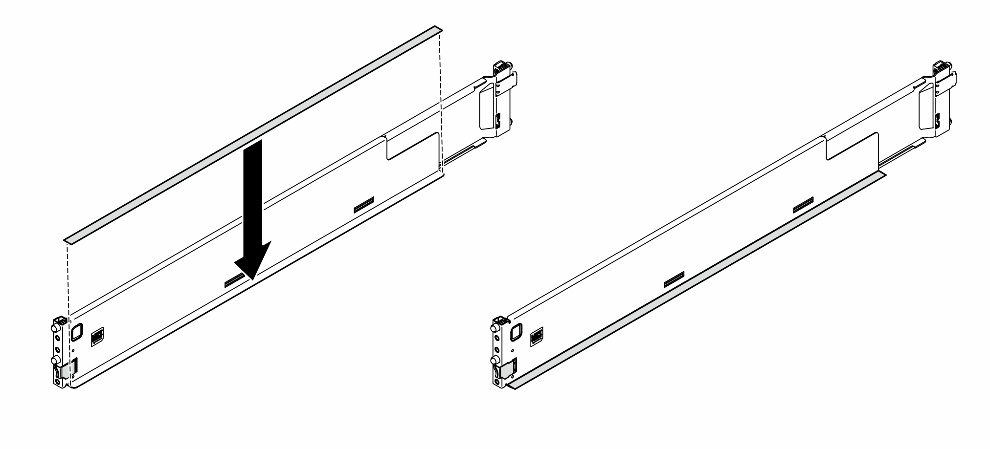
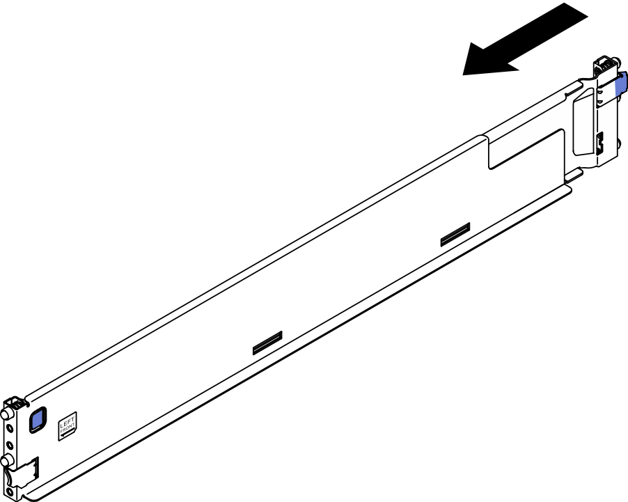
- Grab the rear end of one rail and compress it to the minimal length.Figure 5. Shorten the rail
- Align the rear end of the rail with the holes in the rear EIA flanges; then, push the rail until the latch clicks into place around the edge of the EIA flange.Figure 6. Installation of the rear end of the rail
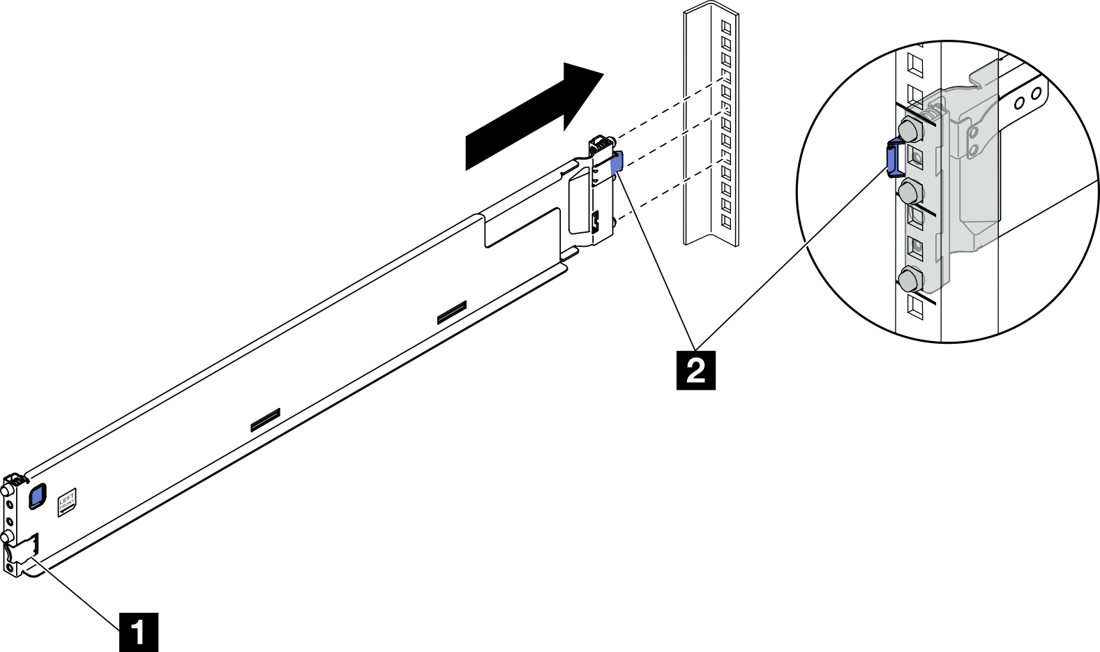
1 Front latch 2 Rear latch - Install the front end of the rail.
 Pull the rail towards the front.
 Press and hold the blue button to open the front latch.
 Align the pins on the front end of the rail with the holes in the front EIA flange and pull the rail forward; then, release the blue button so the latch catches over the EIA flange.
Figure 7. Installation of the front end of the rail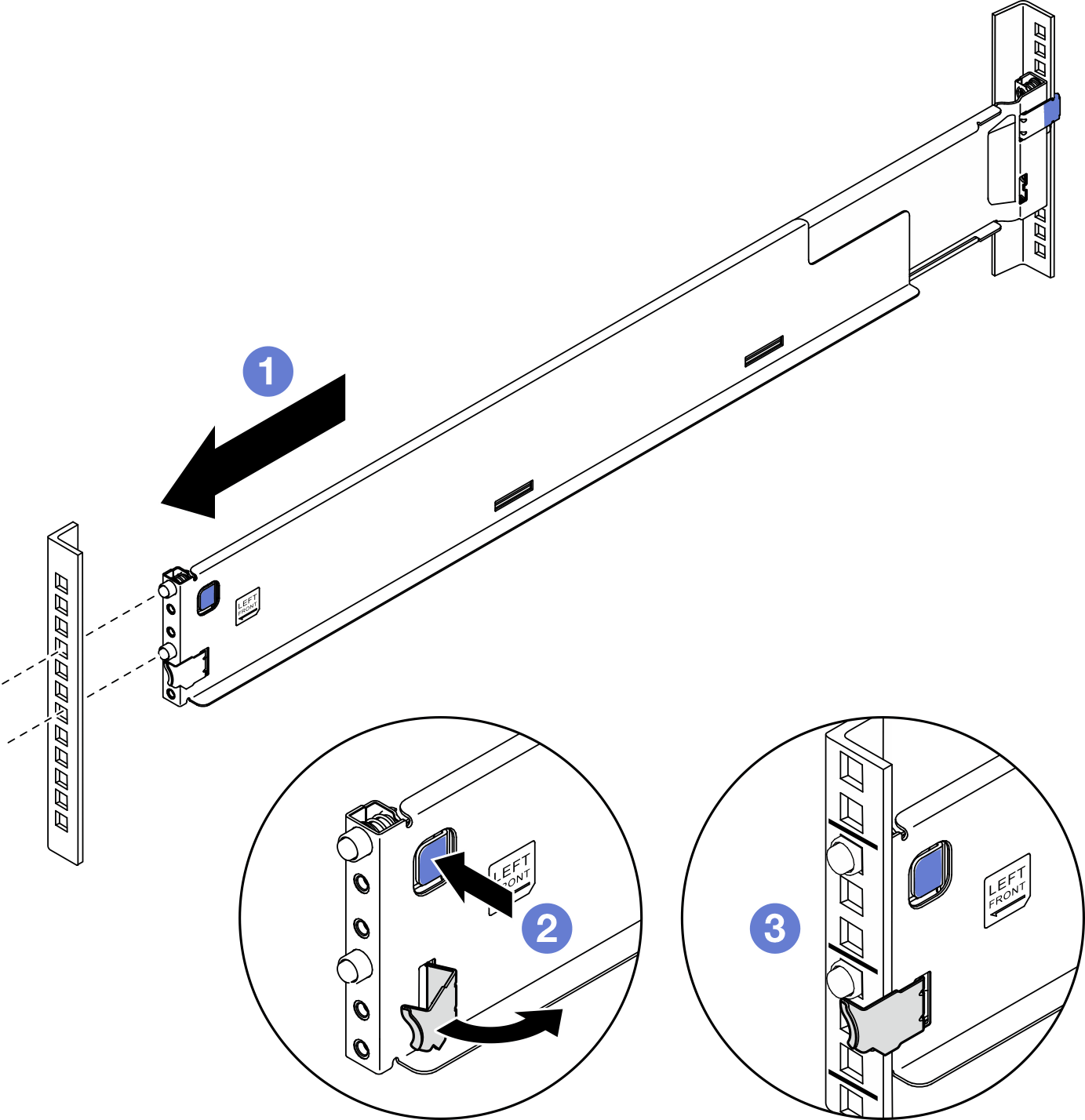 Note
NoteTo make sure the rails are secured to square hole racks, examine the pins to see if the collars are fully in the mounting flange holes. If not, gently shake the rails until all the collars are visible in the mounting flange holes. Examine both ends to make sure the rails are secured.
Figure 8. Pins in square mounting flange holes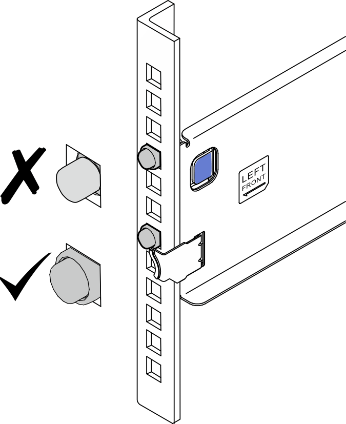 Figure 9. Pins in round mounting flange holes
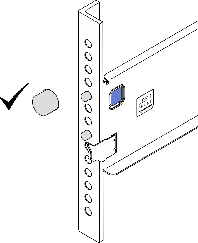
- Grab the rear end of one rail and compress it to the minimal length.
- Align and place the chassis onto the rails mounted in the rack; then, slide it into the rack.Figure 10. Installation of the server into the rails
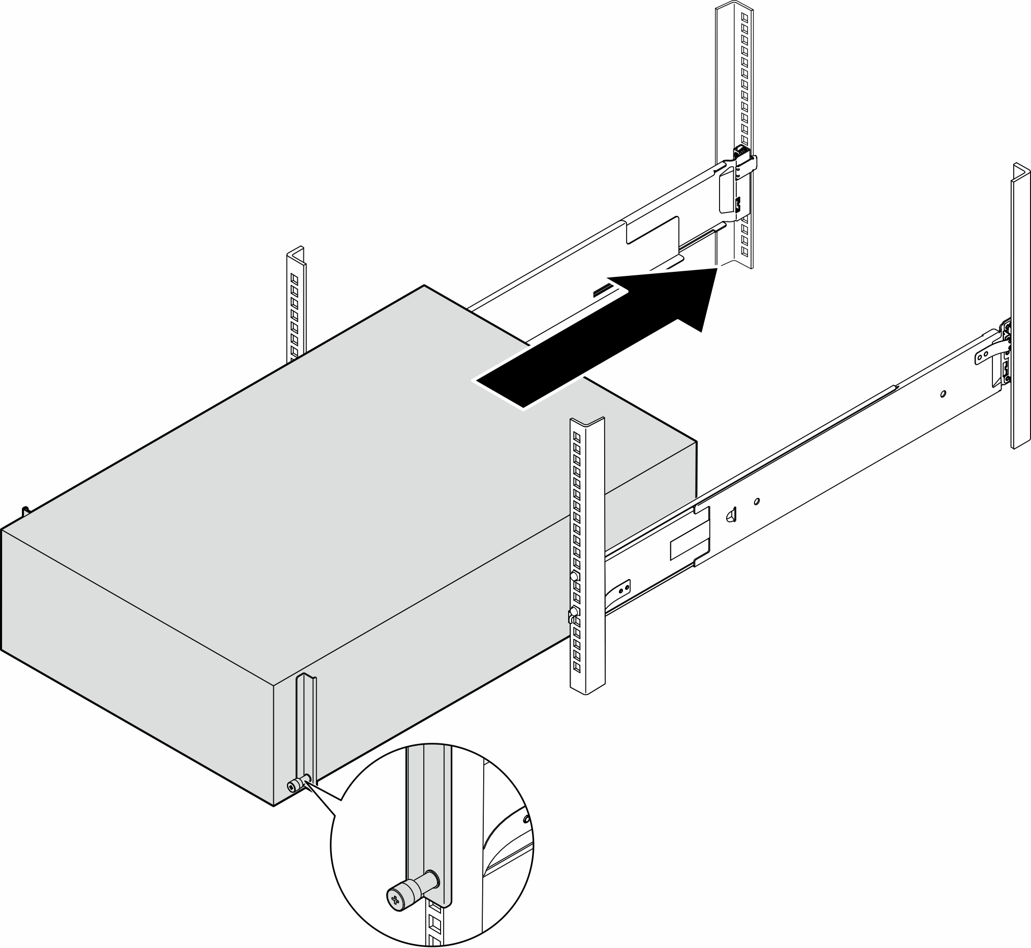
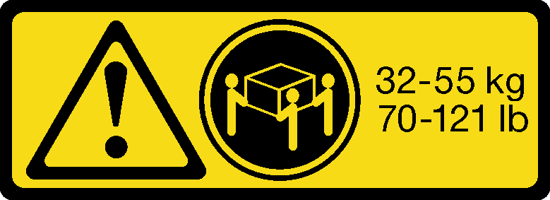 CAUTIONFor tower server installation, use safe practices when lifting.
Reconnect the power cords and any cables that were removed.
Power on the server and any peripheral devices. See Power on the server.
Update the server configuration. See Complete the parts replacement.