Replacing the simple-swap backplate
This procedure applies only to 4U server models with non-hot-swap power supplies.
To install the simple-swap backplate on 4U server models with non-hot-swap power supplies, complete the following steps.
- Read the safety information in Safety and Installation guidelines.
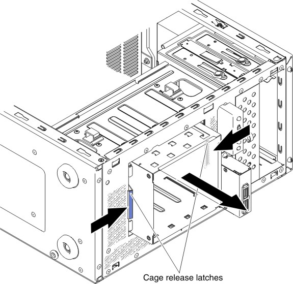
- Press and hold the hard disk drive cage release latches to pull the drive cage out.Figure 1. Hard disk drive cage removal for 4U server model with non-hot-swap power supplies
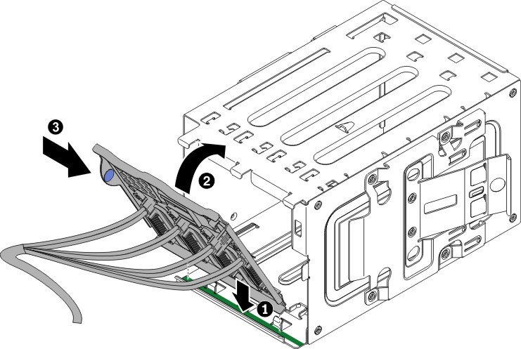
- Align the bottom edge of the simple-swap backplate between the tabs and the bottom edge of the hard disk drive cage (area colored in green), then rotate the backplate toward the hard disk drive cage and slide it inwards.Figure 2. Simple-swap backplate installation in hard disk drive cage for 4U server model with non-hot-swap power supplies
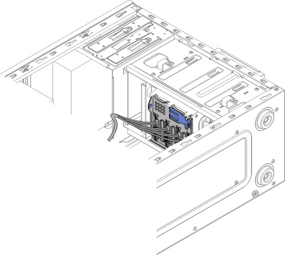
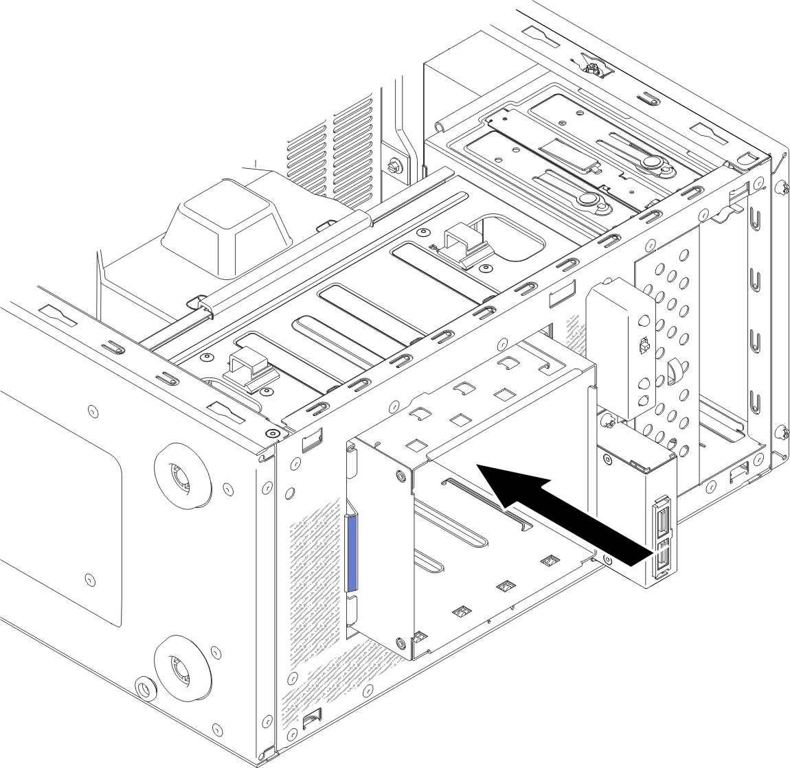
- Slide the hard disk drive cage into the opening in the front of the chassis till half in.Figure 3. Sliding hard disk drive cage half in into chassis for 4U server model with non-hot-swap power supplies
- Connect the hard disk drive power cables to the backplate (connector P3 to bay 3, connector P4 to bay 4, connector P5 to bay 5, and connector P6 to bay 6).
- Connect the hard disk drive signal cables to the SATA connectors on the system board or the connector on the adapter (if one is installed).NoteIn the LSI RAID utility, SATA 1 represents hard disk drive in drive bay two and SATA 2 represents hard disk drive in drive bay one (see
Replacing a simple-swap hard disk drive). The following illustration shows the SATA connectors on the system board:
Figure 4. SATA connector location on system board for 4U server model with non-hot-swap power supplies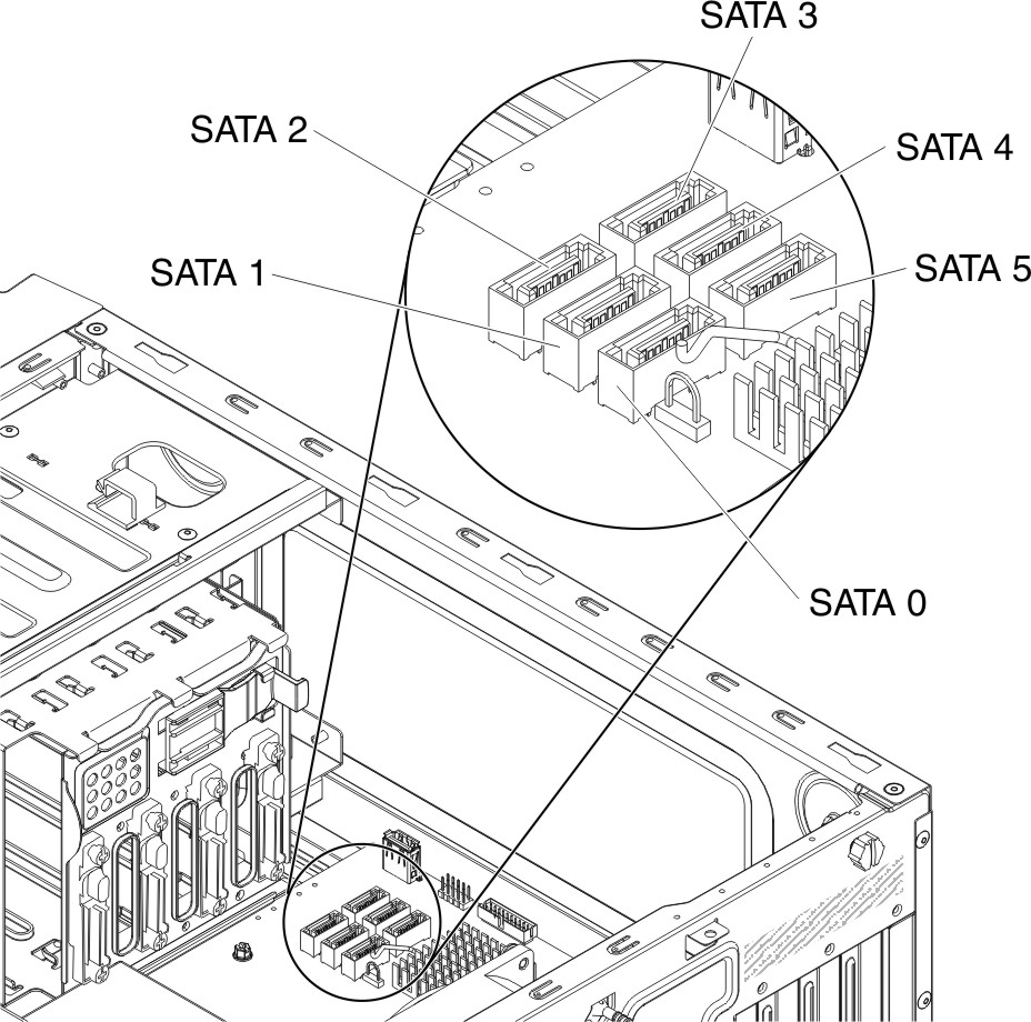
- Push hard disk drive cage in until the release latches click into place.Figure 5. Pushing hard disk drive cage into chassis for 4U server model with non-hot-swap power supplies
- Install the simple-swap hard disk drives that you removed from the hard disk drive cage (see Replacing a simple-swap hard disk drive).
- Install the air baffle (see Replacing the air baffle).
- Install the side cover (see Replacing the side cover).
- Stand the server back up in its vertical position.
- Install bezel (see Replacing the bezel).
- Reconnect the external cables and power cords; then, turn on the attached devices and turn on the server.
Give documentation feedback