Removing the operator information panel assembly
Use this information to remove the operator information panel assembly
To remove the operator information panel assembly on 4U server models with non-hot-swap power supplies, complete the following steps. For the 5U server model with hot-swap power supplies, please see the next sub-section.
- Read the safety information in Safety and Installation guidelines.
- Turn off the server and all peripheral devices; then, disconnect the power cords and all external cables.
- Remove the bezel (see Removing the bezel).
- Carefully turn the server on its side so that it is lying flat, with the cover facing up.AttentionDo not allow the server to fall over.
- Remove the side cover (see Removing the side cover).
- Remove the air baffle (see Removing the air baffle).
- Disconnect the operator information panel assembly cable from the system board, and note the routing of the cable (see System-board internal connectors for the location of the operator information panel assembly connector).
- Stand the server back up in its vertical position.
- Press on top of the operator information panel assembly and rotate the assembly toward the bottom of the server; then, remove the operator information panel assembly from the chassis.Figure 1. Operator information panel assembly removal for 4U server model with non-hot-swap power supplies
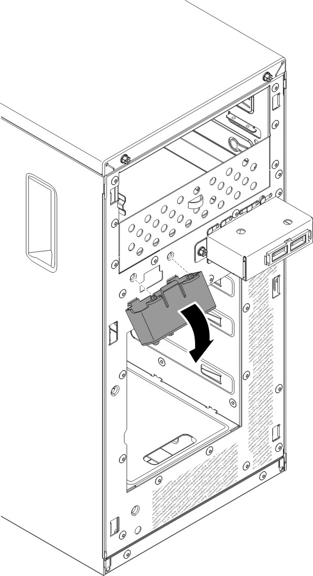 NoteCarefully pull the cable out from the opening. Do not allow the LED to disconnect from the operator information panel assembly.
 - If you are instructed to return the operator information panel assembly, follow all packaging instructions, and use any packaging materials for shipping that are supplied to you.
To remove the operator information panel assembly on the 5U server model with hot-swap power supplies, complete the following steps. For 4U server models with non-hot-swap power supplies, please see the above sub-section.
- Read the safety information in Safety and Installation guidelines.
- Turn off the server and all attached devices; then, disconnect all power cords and external cables.
- Unlock and remove the side cover (see Removing the side cover).
- Remove the lower bezel (see Removing the lower bezel).
- Remove the upper bezel (see Removing the upper bezel).
- Slide the drives in bay 1 and bay 2 forward slightly (see Removing a DVD drive and Removing a tape drive for more information). It is not necessary to remove these drives.
- Carefully turn the server on its side so that it is lying flat, with the system board facing up.AttentionDo not allow the server to fall over.
- Remove the hot-swap power supplies and the hot-swap power-supply cage (see Removing the hot-swap power supply) and Removing the hot-swap power supply cage).
- Disconnect the operator information panel assembly cable from the system board, and note the routing of the cable (see System-board internal connectors for the location of the operator information panel assembly connector).
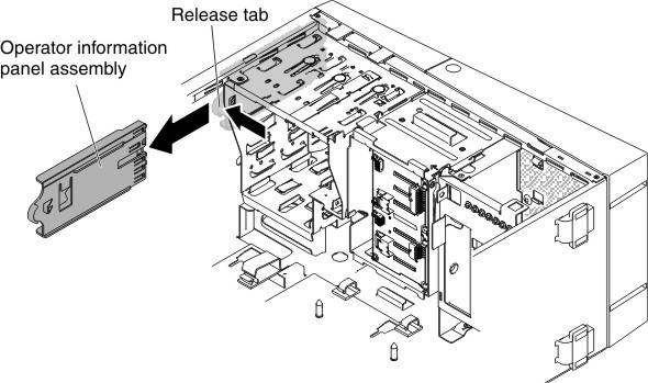
- Press on the release tab of the operator information panel assembly and pull the assembly toward the rear of the server; then, remove the operator information panel assembly from the chassis.Figure 2. Operator information panel assembly removal for 5U server model with hot-swap power supplies
- If you are instructed to return the operator information panel assembly, follow all packaging instructions, and use any packaging materials for shipping that are supplied to you.
Give documentation feedback