Replacing the front USB connector assembly
Use this information to replace the front USB connector assembly
To install the front USB connector assembly on the 4U server model with non-hot-swap power supplies, complete the following steps. For 5U server models with hot-swap power supplies, please see the next sub-section.
- Read the safety information in Safety and Installation guidelines.
- Carefully insert the front USB cable through the opening in the front of the chassis.
- Place the tab on the bottom edge of the USB housing into the bottom of the opening in the chassis.Figure 1. Front USB connector assembly installation for 4U server model with non-hot-swap power supplies
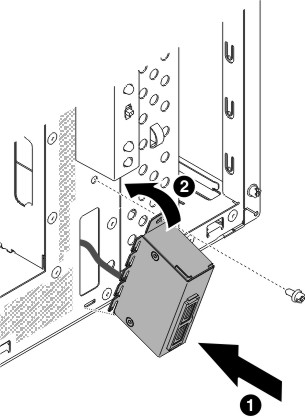
- Tilt the top of the USB housing into position to the end.
- Secure the front USB housing with the screw.
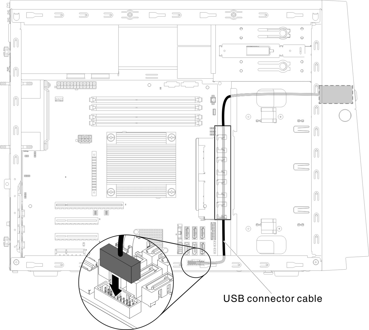
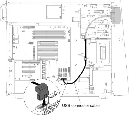
- Reroute and connect the front USB cable to the front USB connector on the system board (see System-board internal connectors for the location of the front USB connector).NoteDisconnection of the SATA cables is suggested if any of them interferes with the process.Figure 2. Front USB cable installation for 4U server model with non-hot-swap power supplies
- Install the air baffle (see Replacing the air baffle).
- Install the side cover (see Removing the side cover).
- Stand the server back up in its vertical position.
- Install bezel (see Replacing the bezel).
- Reconnect the external cables and power cords; then, turn on the attached devices and turn on the server.
To install the front USB connector assembly on the 5U server model with hot-swap power supplies, complete the following steps. For 4U server models with non-hot-swap power supplies, please see the above sub-section.
- Read the safety information in Safety and Installation guidelines.
- Carefully insert the front USB cable through the opening in the front of the chassis.
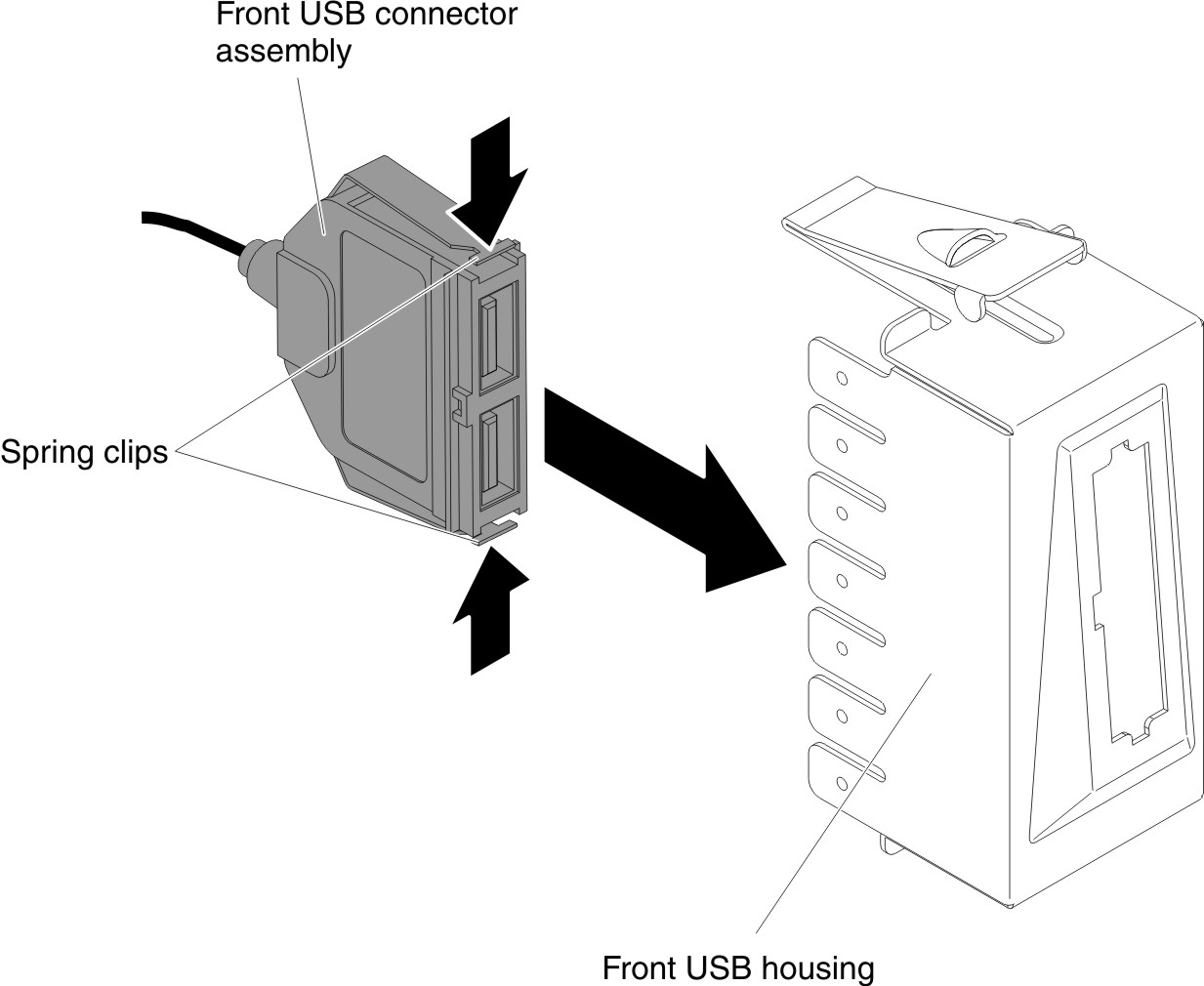
- Squeeze the spring clips on the sides of the front USB connector assembly and insert the assembly into the housing through the back of the housing.Figure 3. Front USB connector assembly installation for 5U server model with hot-swap power supplies (1)
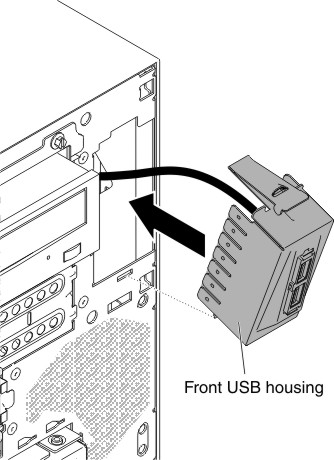
- Place the bottom edge of the housing into the bottom of the opening in the chassis; then, tilt the top of the housing into position until it clicks into place.Figure 4. Front USB connector assembly installation for 5U server model with hot-swap power supplies (2)
- Carefully turn the server on its side so that it is lying flat, with the cover facing up.AttentionDo not allow the server to fall over.
- Reroute and connect the front USB cable to the front USB connector on the system board (see System-board internal connectors for the location of the front USB connector).NoteRemember to route the cabling through the cable clips.Figure 5. Front USB cable installation for 5U server model with hot-swap power supplies
- Install the hard disk drive fan duct (see Replacing the hard disk drive fan duct).
- Stand the server back up in its vertical position.
- Install the upper bezel (see Replacing the upper bezel).
- Install the lower bezel (see Replacing the lower bezel).
- Install and lock the side cover (see Replacing the side cover).
- Reconnect the external cables and power cords; then, turn on the attached devices and turn on the server.
Give documentation feedback