Replacing the operator information panel assembly
Use this information to replace the operator information panel assembly
To install the operator information panel assembly on 4U server models with non-hot-swap power supplies, complete the following steps. For the 5U server model with hot-swap power supplies, please see the next sub-section.
- Read the safety information in Safety and Installation guidelines.
- Reroute the operator information panel assembly cable into the opening.NoteCarefully pull the cable out from the opening. Do not allow the LED to disconnect from the operator information panel assembly.
- Insert the bottom tabs of the operator information panel assembly into the corresponding holes and rotate the assembly toward the chassis.Figure 1. Operator information panel assembly installation for 4U server model with non-hot-swap power supplies
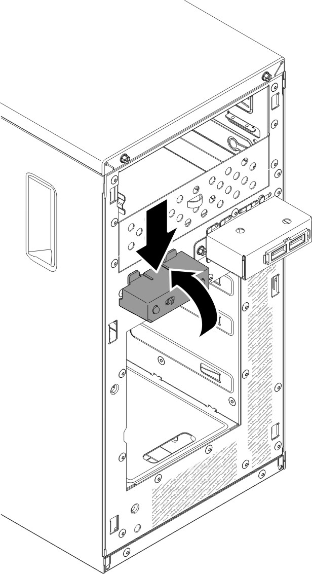
- Push the operator information panel assembly toward the chassis until it clicks into place.
- Reroute and connect the operator information panel assembly cable to the system board (see System-board internal connectors for the location of the operator information panel assembly connector).
- Install the air baffle (see Replacing the air baffle).
- Install the side cover (see Replacing the side cover).
- Stand the server back up in its vertical position.
- Install bezel (see Replacing the bezel).
- Reconnect the external cables and power cords; then, turn on the attached devices and turn on the server.
To install the operator information panel assembly on the 5U server model with hot-swap power supplies, complete the following steps. For 4U server models with non-hot-swap power supplies, please see the above sub-section.
- Read the safety information in Safety and Installation guidelines.
- Carefully turn the server on its side so that it is lying flat.AttentionDo not allow the server to fall over.
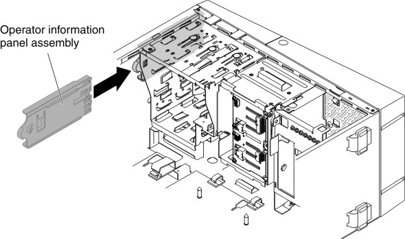
- Position the front end of the operator information panel assembly in the channel above bay 1.
- Push the operator information panel assembly toward the front of the chassis until it clicks into place.Figure 2. Operator information panel assembly installation for 5U server model with hot-swap power supplies
- Reroute and connect the operator information panel assembly cable to the system board (see System-board internal connectors for the location of the operator information panel assembly connector).
- Install the power-supply cage and the power supplies (see Replacing the hot-swap power supply cage and Replacing the hot-swap power supply).
- Push the drives in bay 1 and bay 2 into the drive bays (see Replacing the DVD drive and Replacing the tape drive for more information).
- Stand the server back up in its vertical position.
- Install the upper bezel (see Replacing the upper bezel).
- Install the lower bezel (see Replacing the lower bezel).
- Install and lock the side cover (see Replacing the side cover).
- Reconnect the external cables and power cords; then, turn on the attached devices and turn on the server.
Give documentation feedback