Memory rank sparing
Sparing enables a failing rank to be replaced by ranks installed in an unoccupied space. An unused spare rank on the channel can be used to copy the contents of a failing rank on that channel.
You can enable rank sparing memory in the Setup utility (see Starting the Setup utility).
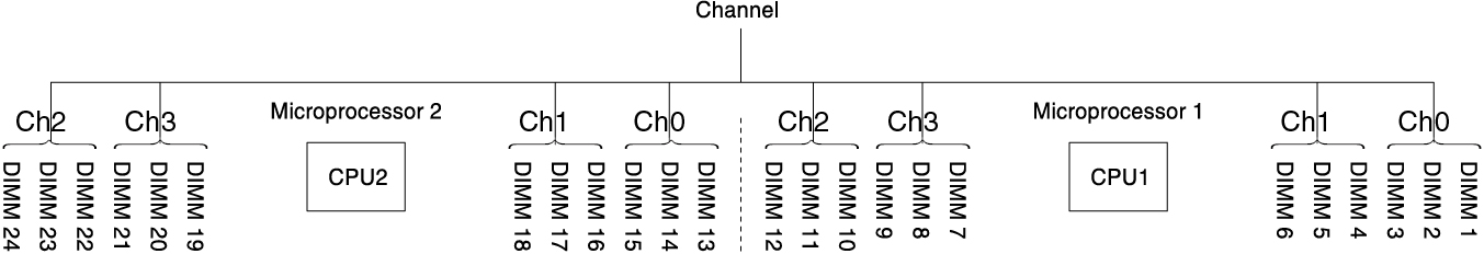
The following diagram lists the DIMM connectors on each memory channel.
Figure 1. Connectors on each memory channel
Note
You can install DIMMs for the microprocessor 2 once the microprocessor 2 is installed. You do not need to wait until all of the DIMM connectors for microprocessor 1 are filled.
The following table shows the installation sequence for memory rank sparing mode:
| Number of DIMMs | Number of installed microprocessor | DIMM connector |
|---|---|---|
| First pair of DIMMs | 1 | 1, 2 |
| Second pair of DIMMs | 1 | 4, 5 |
| Third pair of DIMMs | 1 | 8, 9 |
| Fourth pair of DIMMs | 1 | 11, 12 |
| Fifth pair of DIMMs | 1 | 7, 10 |
| Sixth pair of DIMMs | 1 | 3, 6 |
| Seventh pair of DIMMs | 2 | 13, 14 |
| Eighth pair of DIMMs | 2 | 16, 17 |
| Ninth pair of DIMMs | 2 | 20, 21 |
| Tenth pair of DIMMs | 2 | 23, 24 |
| Eleventh pair of DIMMs | 2 | 19, 22 |
| Twelfth pair of DIMMs | 2 | 15, 18 |
Note DIMM connectors 3, 6, 7, 10, 15, 18, 19, and 22 are not used in memory rank sparing mode when UDIMMs are installed in the server. | ||
Give documentation feedback