Install an I/O module board
Follow instructions in this section to install an I/O module board.
About this task
To avoid potential danger, make sure to read and follow the safety information.
- S002
 CAUTIONThe power-control button on the device and the power switch on the power supply do not turn off the electrical current supplied to the device. The device also might have more than one power cord. To remove all electrical current from the device, ensure that all power cords are disconnected from the power source.
Read Installation Guidelines and Safety inspection checklist to make sure that you work safely.
Touch the static-protective package that contains the component to any unpainted metal surface on the node; then, remove it from the package and place it on a static-protective surface.
Go to Drivers and Software download website for ThinkEdge SE350 V2 to see the latest firmware and driver updates for your server.
Go to Update the firmware for more information on firmware updating tools.
Depending on the specific configuration, the front I/O bezel and I/O module board might look different from the illustrations in this section.
Procedure
- Lower and pivot the I/O module board at an angle to insert it into place; then, make sure the I/O module board is connected with the bridge board.AttentionWhen sliding and inserting the I/O module board into place, make sure to:
- keep the I/O module board under the studs on both sidewalls of the chassis; and
- align and engage the I/O module board with the guide pins on the bottom of the chassis.
Figure 1. Installation of the I/O module board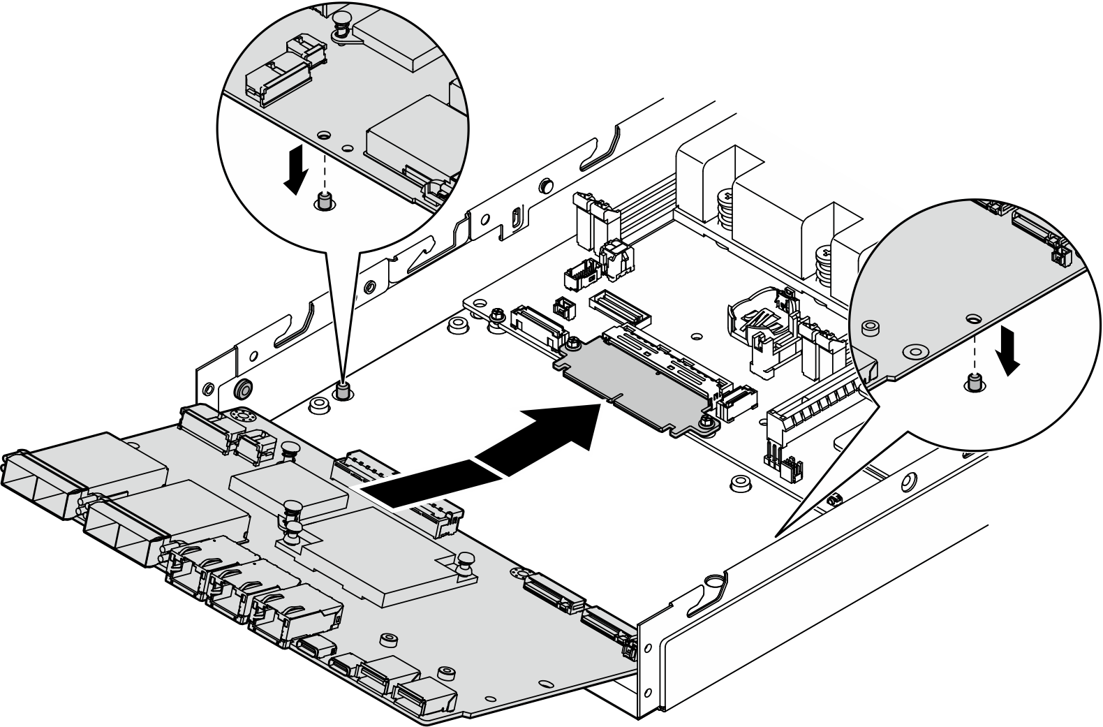
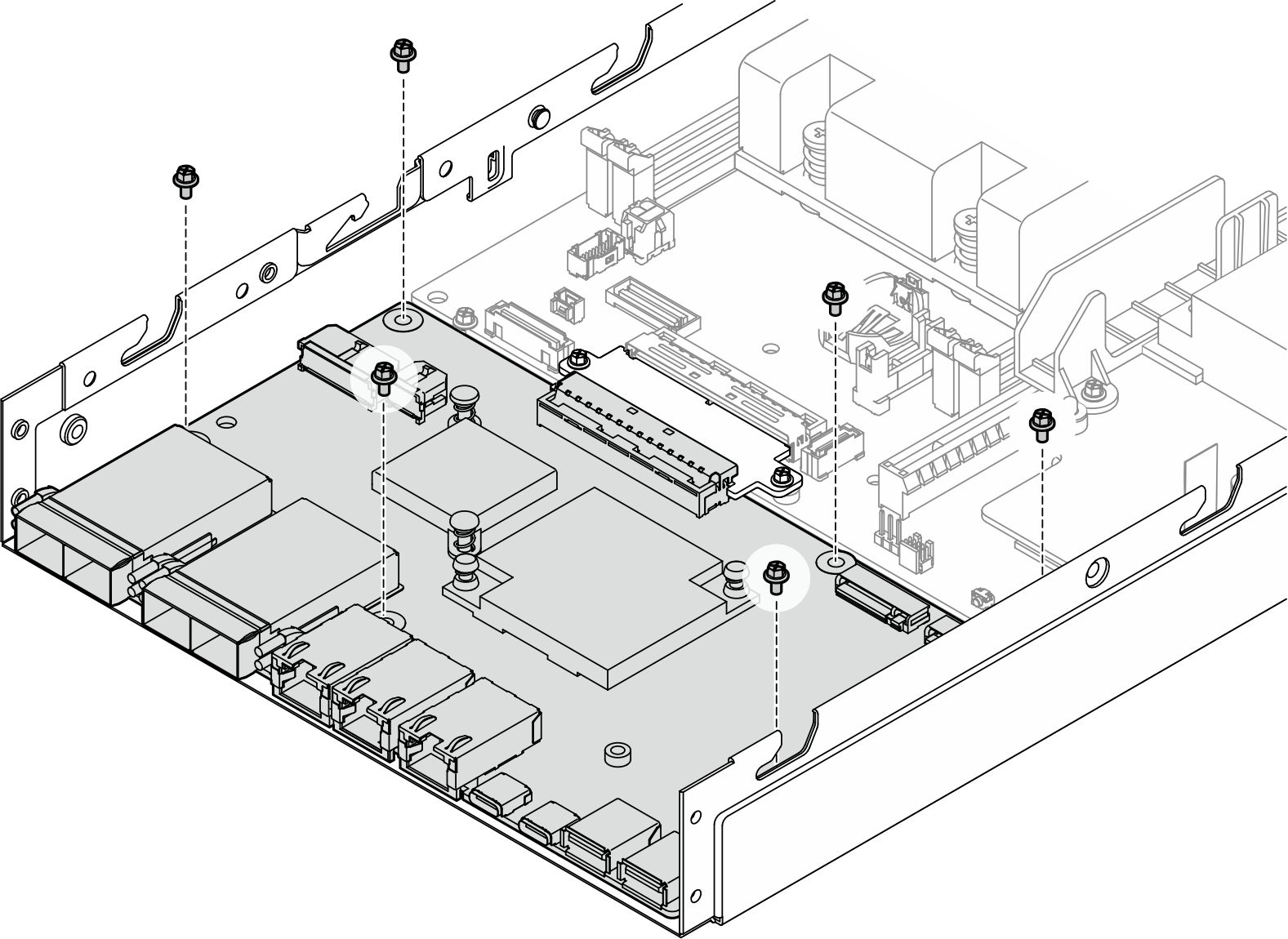
- Tighten the six screws as shown to secure the I/O module board.Figure 2. Installation of the I/O module board screws
After this task is completed
- Connect the I/O-module-board power cable (see Cable routing for the I/O module board).
- Install a front I/O bezel (see Install a front I/O bezel).
- Install a front operator assembly (see Install a front operator assembly).
- Install a drive cage (see Install a drive cage).
- If necessary, install one or both M.2 boot drives onto the I/O module board (see Install an M.2 boot drive).
Proceed to complete the parts replacement (see Complete the parts replacement).