Install a system board (trained technician only)
Follow instructions in this section to install a system board. This procedure must be executed by a trained technician.
About this task
- Removing and installing this component requires trained technicians. Do not attempt to remove or install the part without proper training.
- When replacing the system board, always update the server with the latest firmware or restore the pre-existing firmware. Make sure that you have the latest firmware or a copy of the pre-existing firmware before you proceed.
- When removing the memory modules, label the slot number on each memory module, remove all the memory modules from the system board, and set them aside on a static-protective surface for reinstallation.
- When disconnecting cables, make a list of each cable and record the connectors the cable is connected to, and use the record as a cabling checklist after installing the new system board.
To avoid potential danger, make sure to read and follow the safety information.
- S002
 CAUTIONThe power-control button on the device and the power switch on the power supply do not turn off the electrical current supplied to the device. The device also might have more than one power cord. To remove all electrical current from the device, ensure that all power cords are disconnected from the power source.
 - S012
 CAUTIONHot surface nearby.
Read Installation Guidelines and Safety inspection checklist to make sure that you work safely.
Touch the static-protective package that contains the component to any unpainted metal surface on the node; then, remove it from the package and place it on a static-protective surface.
Go to Drivers and Software download website for ThinkEdge SE350 V2 to see the latest firmware and driver updates for your server.
Go to Update the firmware for more information on firmware updating tools.
Procedure
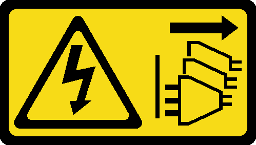
- Insert the system board into the node at an angle as illustrated.Figure 1. Installation of a system board
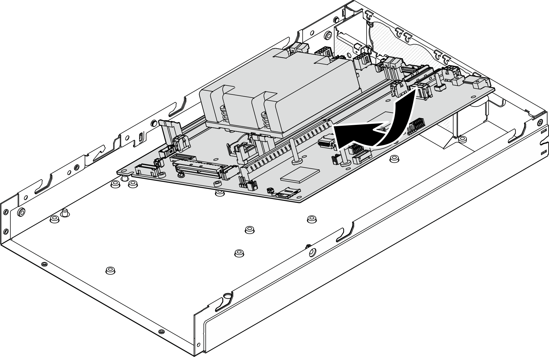
- Carefully slide the system board toward the rear of the node; then, seat the system board onto the guide pins of the chassis.Figure 2. Installation of a system board
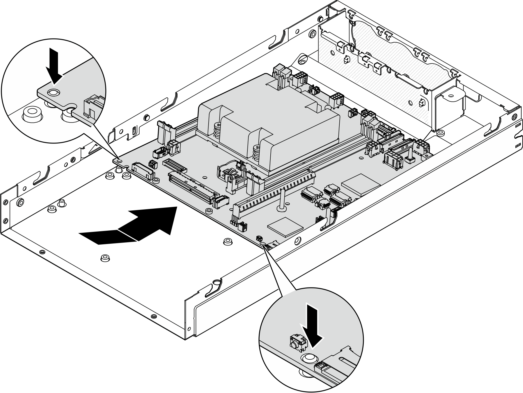
- Tighten the screws and standoffs as illustrated to secure the system board.Figure 3. System board screws
 Note
NoteThe hex standoffs are designed to be used with a common Phillips screwdriver or flat-head screwdriver.
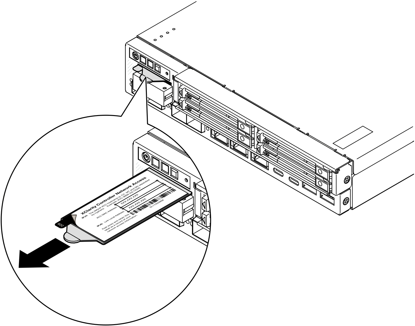
- Peel away the Lenovo XClarity Controller network access label on the process heat sink; then, attach this label to the network access tag on the front of the node.Figure 4. Lenovo XClarity Controller network access label on the pull-out information tab
After this task is completed
- Proceed to install the other components of the system-board assembly.
- Install a bridge board (see Install a bridge board).
- Install an I/O module board (see Install an I/O module board).
- Install a front I/O bezel (see Install a front I/O bezel).
- Reinstall any components that have been removed from the system board and connect all required cables (see related topics in Hardware replacement procedures and Internal cable routing), such as the following.
- Reinstall the power input board module and the power main board and connect the required cables between these two components (see Install a power input board (PIB) module, Install a power module board (PMB), and Cable routing for the power module board and power input board module).
- Reinstall all the required memory modules (see Install a memory module).
- If applicable, reinstall the intrusion switch with cable and connect the cable to the system board(see Install an intrusion switch with cable).
- Reinstall the front operator assembly and connect the cable to the system board (see Install a front operator assembly).
- Reinstall the MicroSD card (see Install a MicroSD card).
- Reinstall the keylock switch with cable and connect the cable to the system board (see Install a keylock switch with cable).
- Reinstall the drive cage and connect the required cables to the system board and the I/O module board (see Install a drive cage and Cable routing for the hot-swap drives).
- Connect and route all the required cables into place (see Internal cable routing).
- Proceed to complete the parts replacement (see Complete the parts replacement).
- Reconnect the power cords and any cables that you removed.
- Reset the system date and time.
- Update the machine type and serial number with the new vital product data (VPD) using the Lenovo XClarity Provisioning Manager (see Update the Vital Product Data (VPD)).Note
- The machine type needs to be updated if the node is to be installed in an enclosure, or is removed from and not to be reinstalled to an enclosure (see Change the machine type for operating in an enclosure).
- Machine type number and serial number can be found on the ID label (see Identify the server and access the Lenovo XClarity Controller).
Update the UEFI, XCC and LXPM firmware to the specific version supported by the server. See Update the firmware.
If applicable, install Lenovo Features on Demand activation key. See the
License Management
section in the XCC documentation compatible with the server at Lenovo XClarity Controller portal page.Update the public key. See the
Update Device Key
section of ThinkShield Edge Mobile Management Application User Guide or ThinkShield Key Vault Portal Web Application User Guide in ThinkEdge Security for more details.Note- The role of Lenovo ID should be Maintenance User to update the public key in ThinkShield Key Vault Portal web interface or ThinkShield mobile app.
- (Lenovo service technician only) See How to update public key after system board replacement for the details.
- Set the TPM policy (see Set the TPM policy).
- Optionally, enable Secure Boot (see Enable UEFI Secure Boot).
Reconfigure the following ThinkEdge security features if necessary.
Change System Lockdown Mode Control status to ThinkShield Portal. See Activate or unlock the system
Enable SED encryption. See Manage the Self Encryption Drive Authentication Key (SED AK).
Recover SED AK. See Manage the Self Encryption Drive Authentication Key (SED AK).
Enable security features. See System Lockdown Mode.
Change the emergency XCC password reset settings. See Emergency XCC Password Reset