Remove the front I/O bezel
Follow instructions in this section to remove a front I/O bezel.
About this task
To avoid potential danger, make sure to read and follow the safety information.
- S002
 CAUTIONThe power-control button on the device and the power switch on the power supply do not turn off the electrical current supplied to the device. The device also might have more than one power cord. To remove all electrical current from the device, ensure that all power cords are disconnected from the power source.
Read Installation Guidelines and Safety inspection checklist to make sure that you work safely.
Remove the shipping bracket or security bezel, if applicable (see Configuration guide); then, power off the server and disconnect the power cords (see Power off the server).
Remove the node from the enclosure or node sleeve, if applicable (see Configuration guide); then, carefully lay the node on a flat, static-protective surface.
Depending on the specific configuration, the front I/O bezel and I/O module board might look different from the illustrations in this section.
Procedure
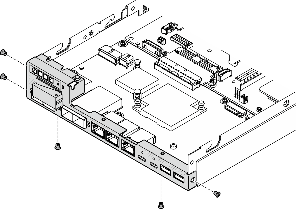
- Remove the five screws that secure the front I/O bezel.Figure 1. Removal of the front I/O bezel screws
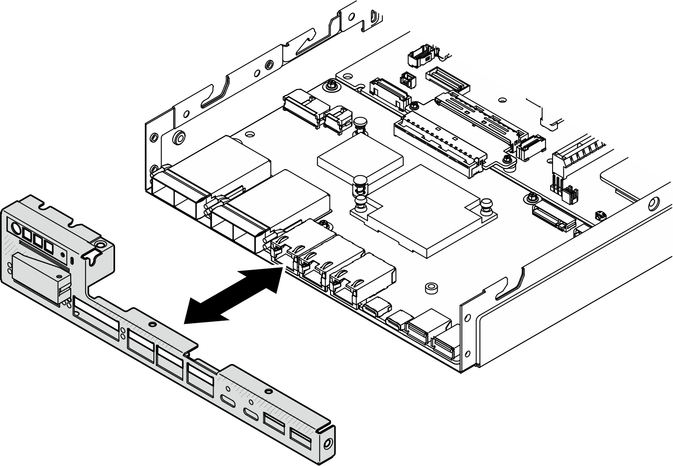
- Remove the front I/O bezel by pulling it away from the node.Figure 2. Removal of the front I/O bezel
After this task is completed
- Install a replacement unit (see Install a front I/O bezel).
- If you are instructed to return the component, follow all of the packaging instructions and use any packaging materials for shipping that are supplied to you.