Remove the system board (trained technician only)
Follow instructions in this section to remove the system board. This procedure must be executed by a trained technician.
About this task
- Removing and installing this component requires trained technicians. Do not attempt to remove or install the part without proper training.
- When replacing the system board, always update the server with the latest firmware or restore the pre-existing firmware. Make sure that you have the latest firmware or a copy of the pre-existing firmware before you proceed.
- When removing the memory modules, label the slot number on each memory module, remove all the memory modules from the system board, and set them aside on a static-protective surface for reinstallation.
- When disconnecting cables, make a list of each cable and record the connectors the cable is connected to, and use the record as a cabling checklist after installing the new system board.
To avoid potential danger, make sure to read and follow the safety information.
- S002
 CAUTIONThe power-control button on the device and the power switch on the power supply do not turn off the electrical current supplied to the device. The device also might have more than one power cord. To remove all electrical current from the device, ensure that all power cords are disconnected from the power source.
 - S012
 CAUTIONHot surface nearby.
Do the following before removing the system board to backup important data:
- Record all system configuration information, such as Lenovo XClarity Controller IP addresses, vital product data, and the machine type, model number, serial number, Universally Unique Identifier, and asset tag of the server.
- If the server has SED installed, maintain a backup of SED AK. See Manage the Self Encryption Drive Authentication Key (SED AK) for more details.
- Use the Lenovo XClarity Essentials OneCLI to save the system configuration to external media.
- Log on XCC Web GUI and backup config to external media.
- Download the XCC Service Data to external media.
Read Installation Guidelines and Safety inspection checklist to make sure that you work safely.
Remove the shipping bracket or security bezel, if applicable (see Configuration guide); then, power off the server and disconnect the power cords (see Power off the server).
Remove the node from the enclosure or node sleeve, if applicable (see Configuration guide); then, carefully lay the node on a flat, static-protective surface.
Procedure
- Remove the three screws and six hex standoffs that secure the system board.Figure 1. Removal of the system board screws and standoffs
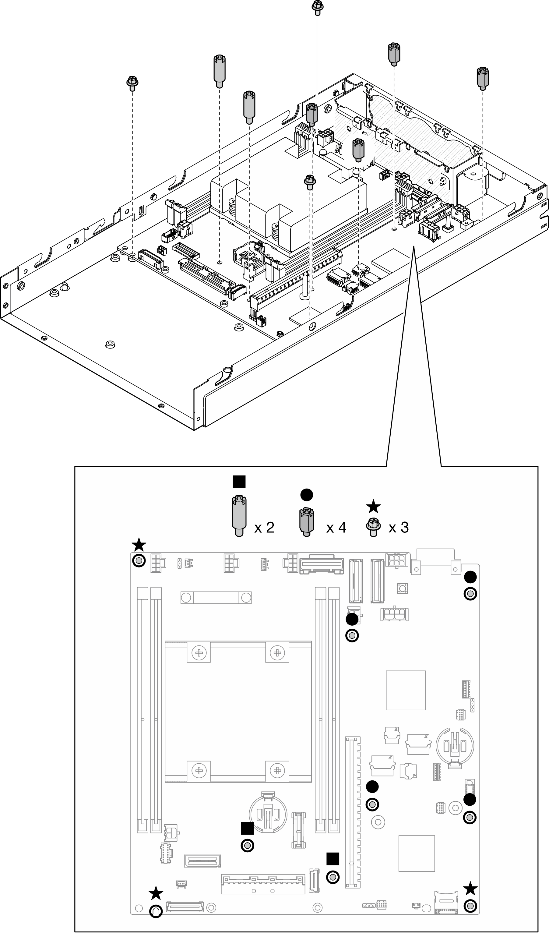 Note
NoteThe hex standoffs are designed to be used with a common Phillips screwdriver or flat-head screwdriver.
- Carefully lift up the system board to disengage it from the chassis pins; then, pull the system board toward the front of the node.Figure 2. Removal of the system board
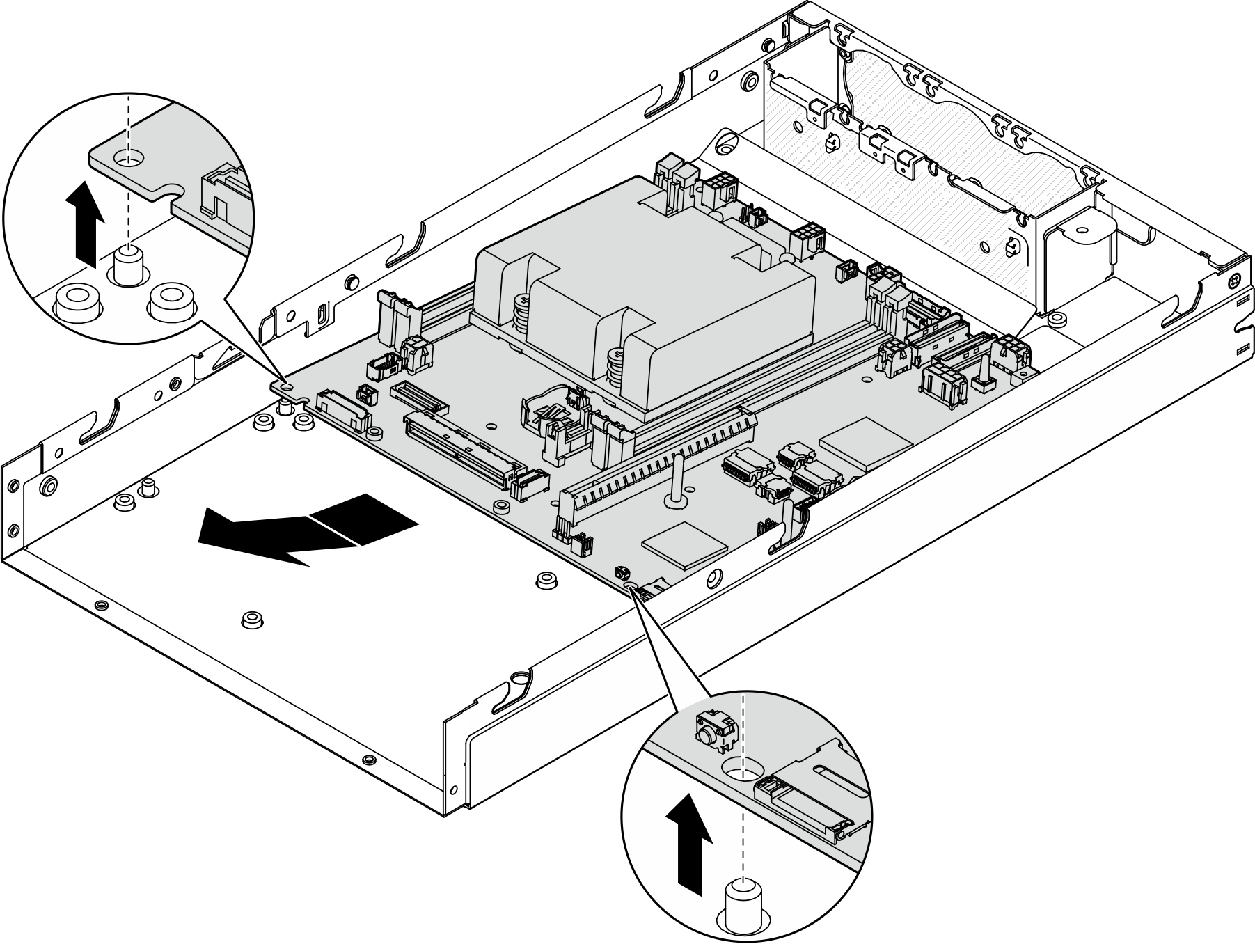
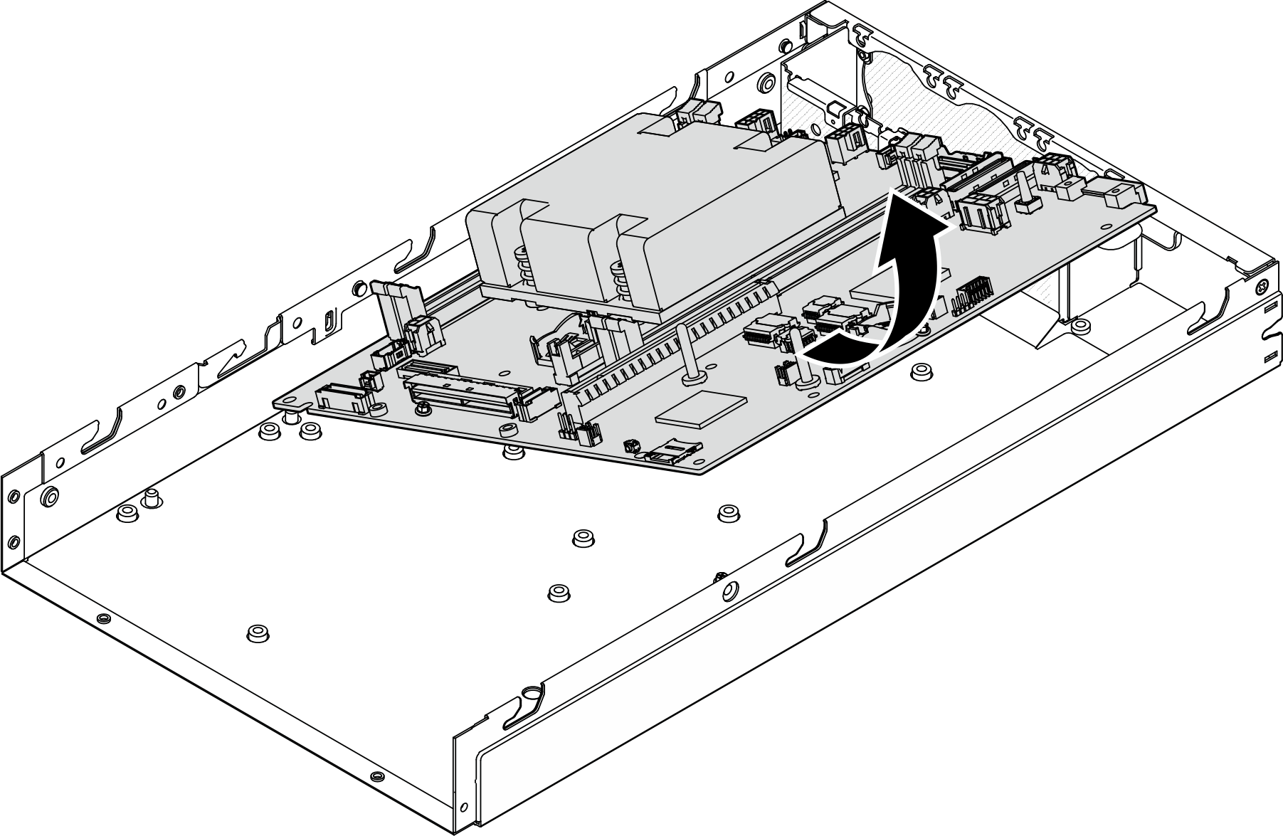
- Pivot the system board at an angle; then, fully remove it from the chassis.Figure 3. Removal of the system board
After this task is completed
- Install a replacement unit (see Install a system board (trained technician only)).
- If you are instructed to return the component, follow all of the packaging instructions and use any packaging materials for shipping that are supplied to you.