
Remove the system board

Follow instructions in this section to remove the system board.

About this task

Important
  • Removing and installing this component requires trained technicians. Do not attempt to remove or install the part without proper training.

  • When replacing the system board, always update the server with the latest firmware or restore the pre-existing firmware. Make sure that you have the latest firmware or a copy of the pre-existing firmware before you proceed.
  • When removing the memory modules, label the slot number on each memory module, remove all the memory modules from the system board, and set them aside on a static-protective surface for reinstallation.

  • When disconnecting cables, make a list of each cable and record the connectors the cable is connected to, and use the record as a cabling checklist after installing the new system board.

Attention

Procedure

  1. Make preparation for this task.
    1. Record all system configuration information, such as Lenovo XClarity Controller IP addresses, vital product data, and the machine type, model number, serial number, Universally Unique Identifier, and asset tag of the server.
    2. If SED encryption is enabled, maintain a backup of SED AK. See Manage the Self Encryption Drive Authentication Key (SED AK).
    3. If applicable, export Lenovo Features on Demand activation key. See the License Management section in the XCC documentation compatible with the server at Lenovo XClarity Controller portal page.
    4. Save the system configuration to an external device with Lenovo XClarity Essentials.
    5. Save the system event log to external media.
    6. Power off the server and peripheral devices and disconnect the power cords and all external cables. See Power off the server.
  2. Remove the following components in the sequence below.
    1. If applicable, remove the WLAN antennas. See Remove the WLAN antennas.
    2. Remove the top cover. See Remove the top cover.
    3. Remove the PMB air baffle. See Remove the PMB air baffle.
    4. Remove the riser assembly. (Before disconnecting the cables of riser assembly, remove the processor air baffle.) See Remove the riser assembly from the node and Remove the processor air baffle and air flow sensor board.
    5. Depending on the model, remove the SMA assemblies or SMA fillers. See Remove the SMA assemblies.
    6. Depending on the configuration, remove the power module board or internal power supply unit. See Remove the power module board (PMB) or Remove the internal power supply unit (AC PMB).
    7. Remove the power input board (PIB) module. See Remove the PIB module.
    8. Remove the top intrusion switch with cable. See Remove the top intrusion switch with cable.
    9. Remove all the memory modules. See Remove a memory module.
    10. If applicable, remove the wireless adapter. See Remove the wireless adapter.
    11. If applicable, remove the MicroSD card from the system board to install it onto the new system board. See Remove the MicroSD card.
  3. Disconnect all the cables from the system board. While disconnecting the cables, make a list of each cable and record the connectors the cable is connected to, and use the record as a cabling checklist after installing the new system board.
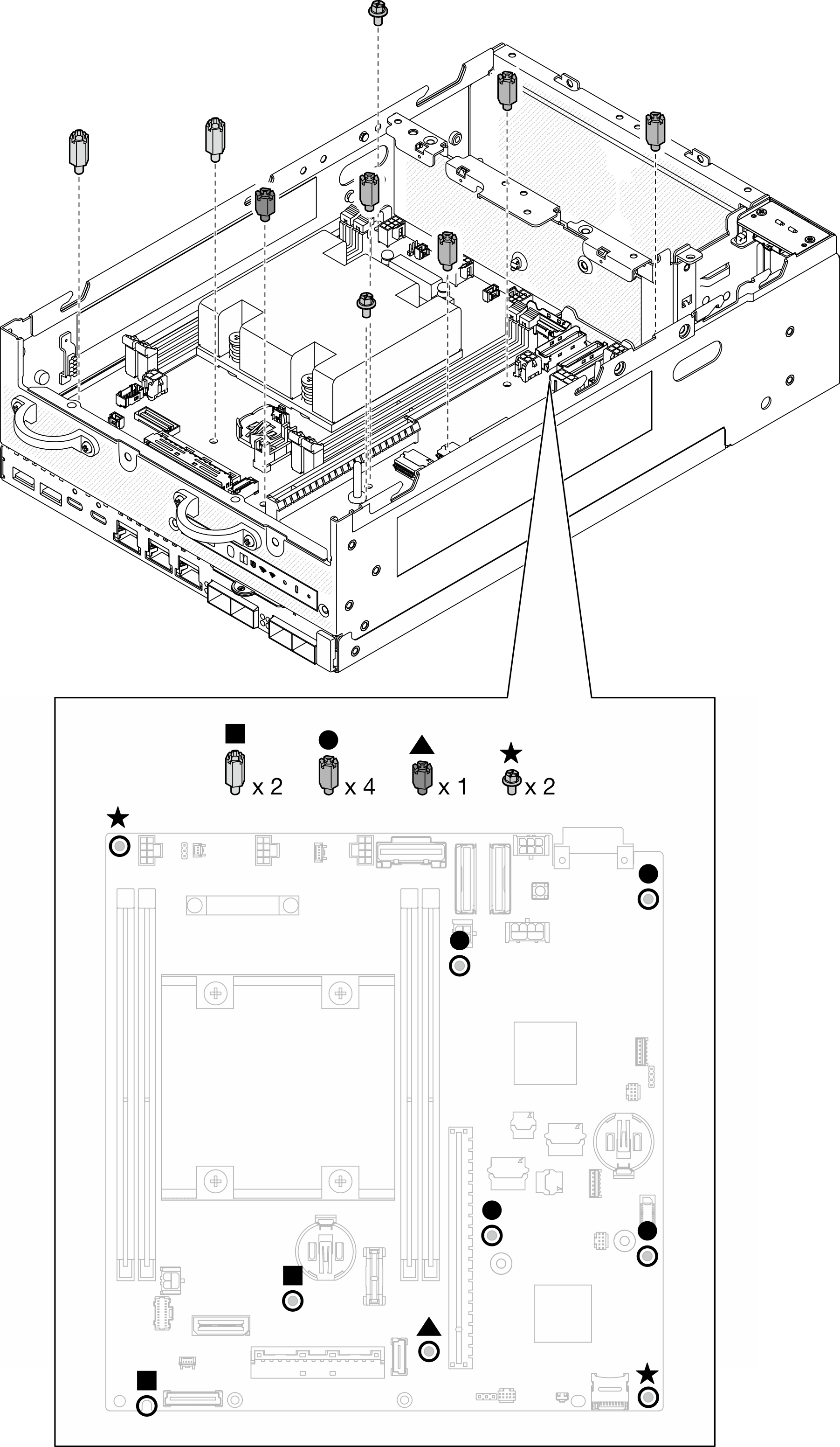
  4. Loosen the seven standoffs and two screws that secure the system board.
    Note
    Loosen the standoffs with a Phillips screwdriver or a flat-head screwdriver.
    Figure 1. The screws and standoffs on the system board

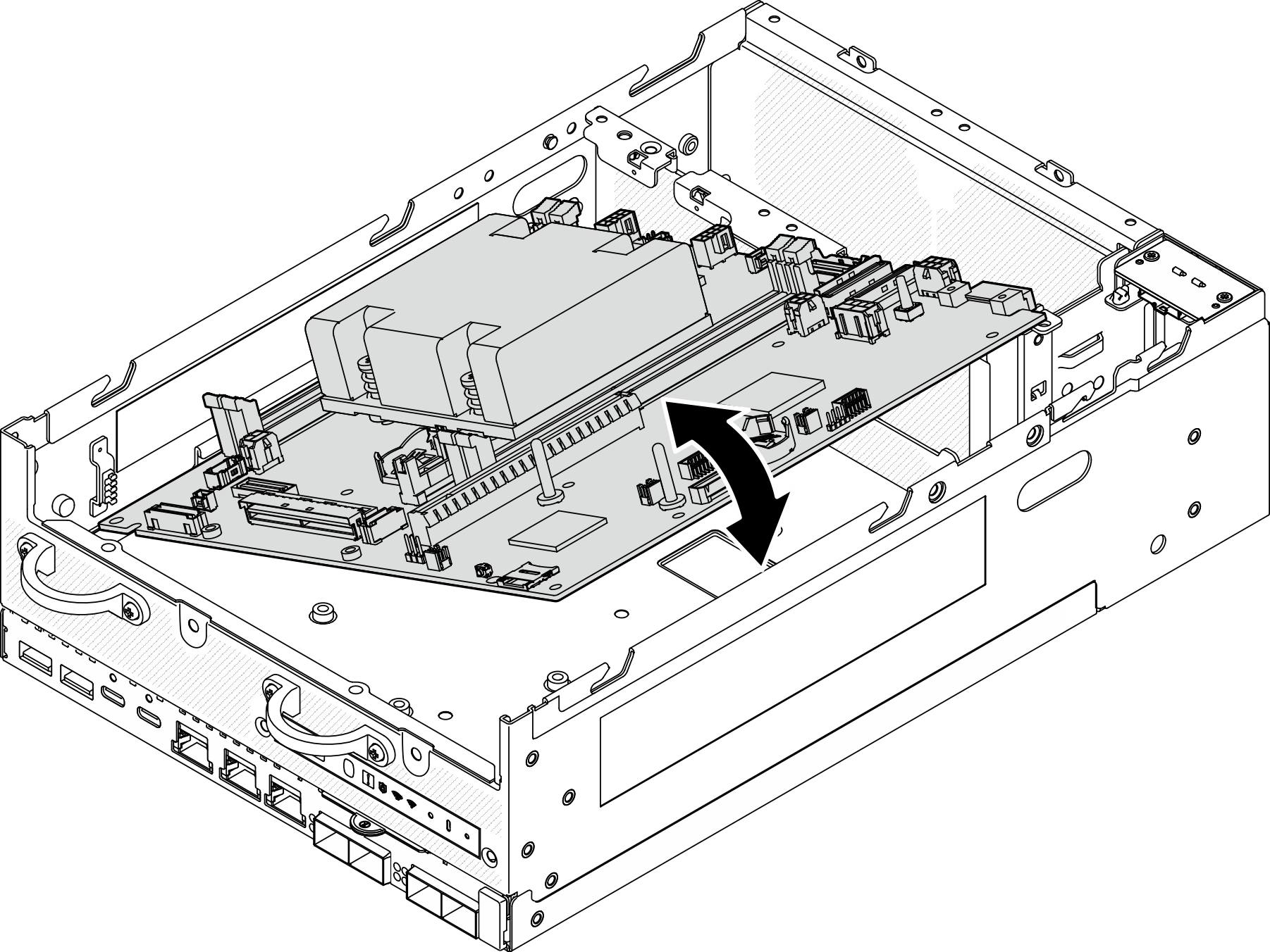
  5. Lift the right end of the system board up; then, remove the system board from the chassis.
    Figure 2. Removing the system board

After this task is completed

  • Install a replacement unit. See Install the system board.

  • If you are instructed to return the component or optional device, follow all packaging instructions, and use any packaging materials for shipping that are supplied to you.

Demo Video

Watch the procedure on YouTube