DC Persistent Memory Module — Memory Mode
In this mode, DCPMMs act as volatile system memory, while DRAM DIMMs act as cache. Only DCPMM capacity is displayed as system memory in this mode.
Figure 1. Processor and memory module layout
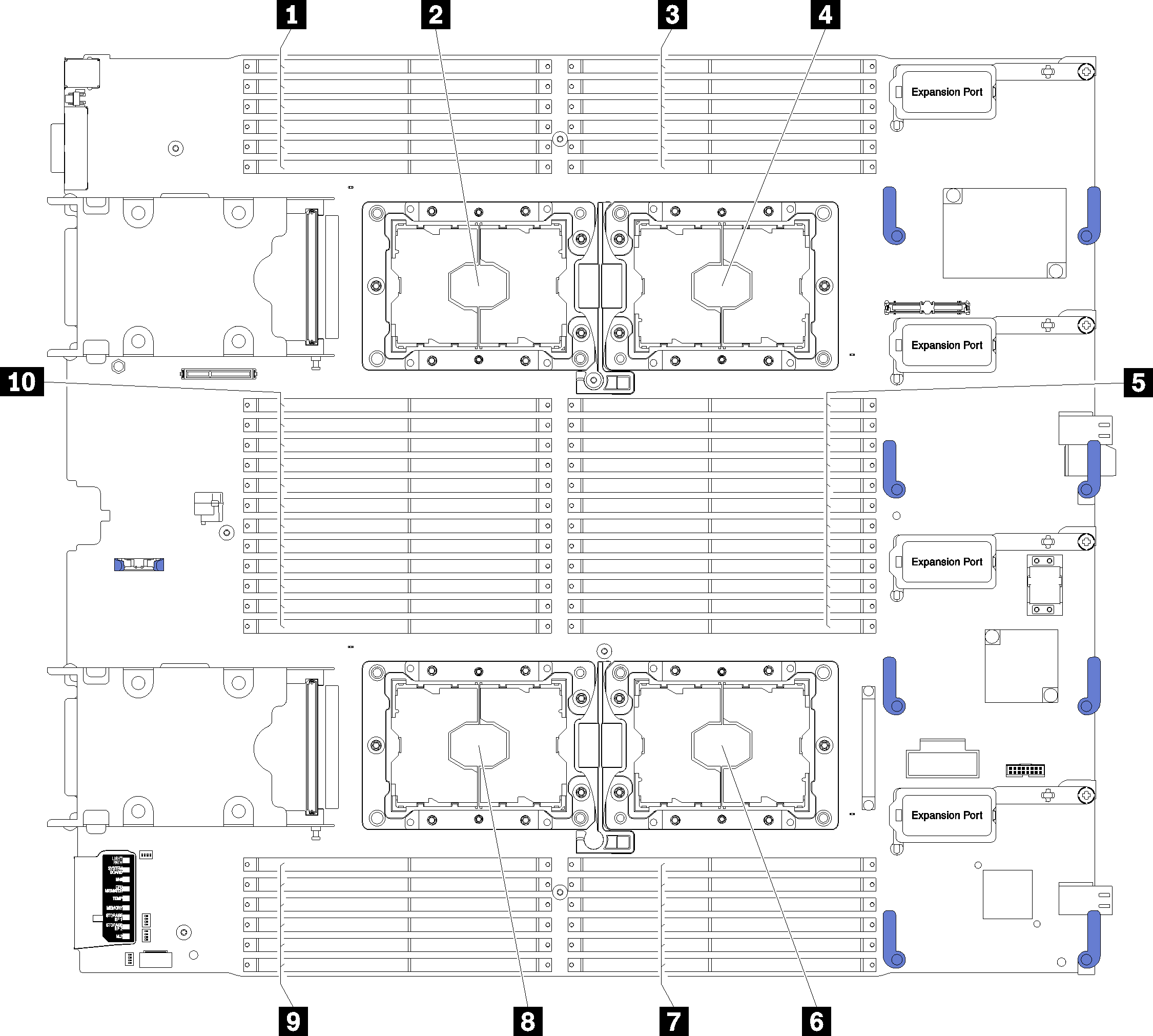
| 1 DIMM 25 – 30 | 6 Processor socket 2 |
| 2 Processor socket 3 | 7 DIMM 19 – 24 |
| 3 DIMM 1 – 6 | 8 Processor socket 4 |
| 4 Processor socket 1 | 9 DIMM 43 – 48 |
| 5 DIMM 7 – 18 | 10 DIMM 31 – 42 |
| Memory controllers | Controller 0 | Controller 1 | |||||||||||
| Channels | Channel 2 | Channel 1 | Channel 0 | Channel 0 | Channel 1 | Channel 2 | |||||||
| Slots | 0 | 1 | 0 | 1 | 0 | 1 | 1 | 0 | 1 | 0 | 1 | 0 | |
| DIMM numbers (processor 1) | 1 | 2 | 3 | 4 | 5 | 6 | 7 | 8 | 9 | 10 | 11 | 12 | |
| DIMM numbers (processor 2) | 13 | 14 | 15 | 16 | 17 | 18 | 19 | 20 | 21 | 22 | 23 | 24 | |
| Memory controllers | Controller 1 | Controller 0 | |||||||||||
| Channels | Channel 2 | Channel 1 | Channel 0 | Channel 0 | Channel 1 | Channel 2 | |||||||
| Slots | 0 | 1 | 0 | 1 | 0 | 1 | 1 | 0 | 1 | 0 | 1 | 0 | |
| DIMM numbers (processor 3) | 25 | 26 | 27 | 28 | 29 | 30 | 31 | 32 | 33 | 34 | 35 | 36 | |
| DIMM numbers (processor 4) | 37 | 38 | 39 | 40 | 41 | 42 | 43 | 44 | 45 | 46 | 47 | 48 | |
The memory mode DIMM population sequences for each supported processor configuration are:
Give documentation feedback