Install the firmware and RoT security module
Follow instructions in this section to install the ThinkSystem V3 Firmware and Root of Trust Security Module (firmware and RoT security module).
About this task
This task must be operated by trained technicians that are certified by Lenovo Service. Do not attempt to remove or install the part without proper training and qualification.
- (Lenovo trained technicians only) After replacing the Firmware and RoT Security Module, update the UEFI, XCC and LXPM firmware to the specific version supported by the server. For detailed information on how to update the firmware, see Tip for replacing a Firmware and RoT Security Module.
Read Installation Guidelines and Safety inspection checklist to ensure that you work safely.
Power off the server and peripheral devices and disconnect the power cords and all external cables. See Power off the server.
Touch the static-protective package that contains the component to any unpainted metal surface on the server; then, remove it from the package and place it on a static-protective surface.
If the server is installed in a rack, remove the server from the rack.
After replacing the Firmware and RoT Security Module, update the firmware to the specific version supported by the server. Make sure that you have the required firmware or a copy of the pre-existing firmware before you proceed.
Go to Drivers and Software download website for ThinkSystem SR250 V3 to see the latest firmware and driver updates for your server.
Go to Update the firmware for more information on firmware updating tools.
Procedure
- Install the Firmware and RoT Security Module. Figure 1. Firmware and RoT Security Module installation
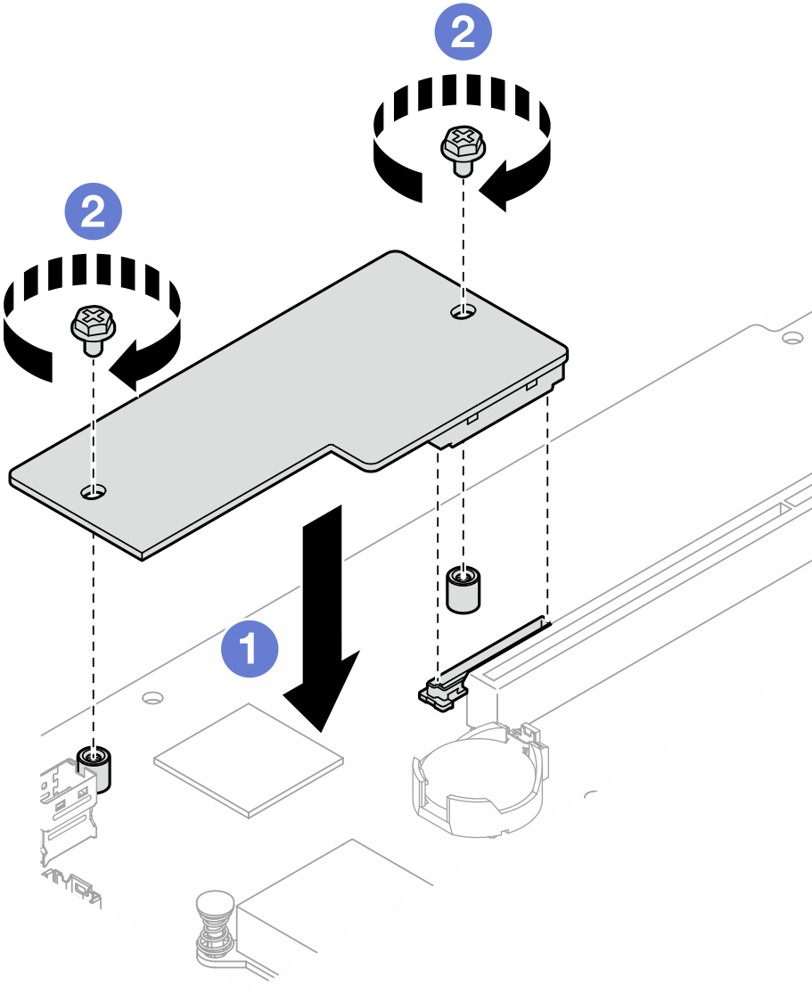
 Lower the Firmware and RoT Security Module onto the system board and ensure that the connector on the module is correctly inserted into the slot on the system board.
 Tighten the two screws to secure the Firmware and RoT Security Module in place.
After you finish
Install the PCIe riser assembly. See Install the PCIe riser assembly.
Install the top cover. See Install the top cover.
Complete the parts replacement. See Complete the parts replacement.
Update the UEFI firmware to the transition build before applying any web-posted UEFI image. Download the transition build file and follow the detailed instructions on Must update UEFI firmware to a transition build first after RoT board replacement on SR250 V3, ST50 V3, ST250 V3 (Lenovo service technicians only).
Update the UEFI, XCC and LXPM firmware to the specific version supported by the server. See Tip for replacing a Firmware and RoT Security Module (Lenovo service technicians only).
Perform OneCLI commands or XCC actions to restore the UEFI and XCC settings. See OneCLI commands that restore configuration settings or Using XCC to restore the BMC configuration.
- If there is a software (SW) key, for example, XCC FoD key, installed in the system, inject the key again to ensure that the key functions properly. See Using Lenovo Features on Demand.NoteIf you need to replace the system board together with the
Firmware and RoT Security Module, update the VPD before injecting the key. See Update the Vital Product Data (VPD). Set the TPM policy. See Enable TPM.
- Optionally, do the following if needed:
Hide TPM. See Hide/observe TPM.
Update the TPM firmware. See Update the TPM firmware.
Enable UEFI Secure Boot. See Enable UEFI Secure Boot.
Demo video