Remove the system board
Use this information to remove the system board.
About this task
This task must be operated by trained technicians that are certified by Lenovo Service. Do not attempt to remove or install the part without proper training and qualification.
Read Installation Guidelines and Safety inspection checklist to ensure that you work safely.
Power off the server and peripheral devices and disconnect the power cords and all external cables. See Power off the server.
If the server is installed in a rack, remove the server from the rack.
Touch the static-protective package that contains the component to any unpainted metal surface on the server; then, remove it from the package and place it on a static-protective surface.
Procedure
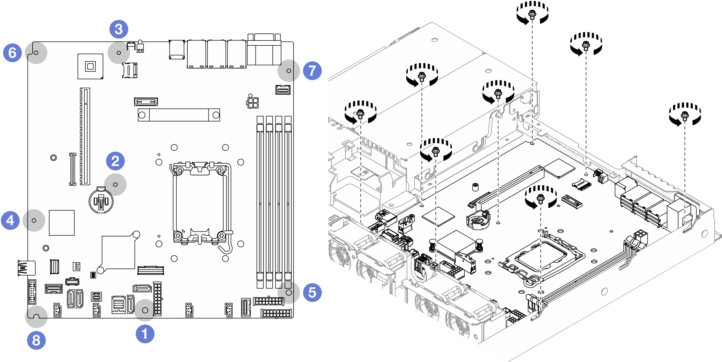
- Remove all eight screws that secure the system board to the chassis.Figure 1. System-board screws location
 Note
Note- The order and locations of screws removal:
 between the SATA connectors and the system power connector
 the lower right side
 near the CMOS battery
 the upper left side
 near NMI button
 the upper right side
 near front USB 3.0 / 2.0 header
 the lower left side
 For reference, the torque which is required for the screws to be fully tightened or removed is 5.0 +/- 0.5 lb-in.
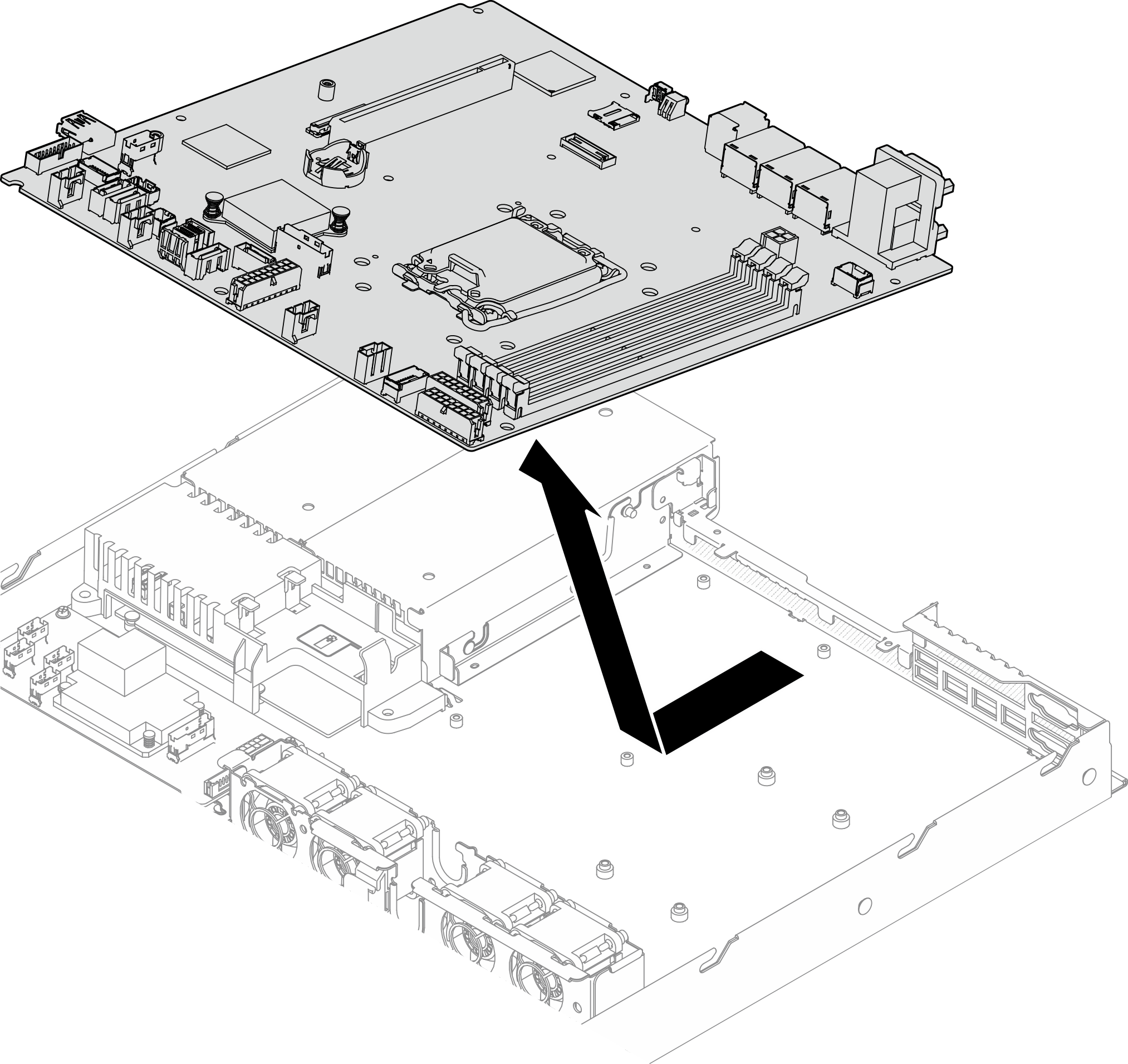
- Slightly lift up the front side of the system board; then, slide the system board towards the front of the server and lift it out of the server.Figure 2. System board removal
After you finish
Install a replacement unit. See Install the system board.
If you are instructed to return the component or optional device, follow all packaging instructions, and use any packaging materials for shipping that are supplied to you.
ImportantBefore you return the system board, make sure that you install the processor socket covers from the new system board. To replace a processor socket cover:Insert the new system board into the chassis. See Install the system board.
Take a socket cover from the processor socket assembly on the new system board and orient it correctly above the processor socket assembly on the removed system board.
Gently press down the socket cover legs to the processor socket assembly, pressing on the edges to avoid damage to the socket pins. You might hear a click on the socket cover when it is securely attached.
Make sure that the socket cover is securely attached to the processor socket assembly.
Demo video