Install the system board
Use this information to install the system board.
About this task
This task must be operated by trained technicians that are certified by Lenovo Service. Do not attempt to remove or install the part without proper training and qualification.
Power off the server and peripheral devices and disconnect the power cords and all external cables. See Power off the server.
If the server is installed in a rack, remove the server from the rack.
Touch the static-protective package that contains the component to any unpainted metal surface on the server; then, remove it from the package and place it on a static-protective surface.
Go to Drivers and Software download website for ThinkSystem SR250 V3 to see the latest firmware and driver updates for your server.
Go to Update the firmware for more information on firmware updating tools.
Procedure
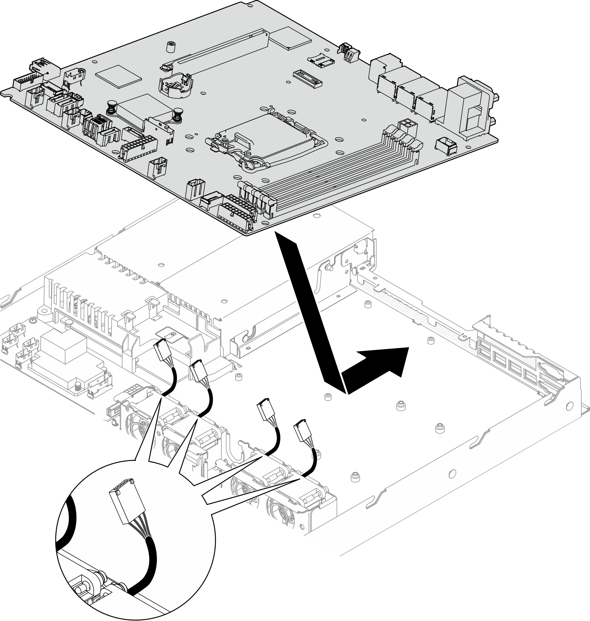
- Align the system board with serial and VGA ports on the rear side of the chassis; then, carefully lower the system board and place the system board flat into the chassis. Make sure the screw slots on the system board match the corresponding slots on the chassis.NoteMove the fan cables aside and make sure these cables will not interfere the installation of the system board.Figure 1. System board installation
- Install all eight screws to secure the system board to the chassis according to the installation orders as shown.Figure 2. System-board screws location
 Note
Note- The order and locations of screws installation :
 the lower left side
 near front USB 3.0 / 2.0 header
 the upper right side
 near NMI button
 the upper left side
 near the CMOS battery
 the lower right side
 between the SATA connectors and the system power connector
 For reference, the torque which is required for the screws to be fully tightened or removed is 5.0 +/- 0.5 lb-in.
After you finish
Install the firmware and RoT security module. See Install the firmware and RoT security module
Install the processor. See Install the processor.
Install the heat sink. See Install the heat sink.
Install the memory modules. See Install a memory module.
Connect the front I/O module cables to the system board. See Front I/O module cable routing.
Connect the fan cables to the system board by pressing it down until it clicks. See Fan cable routing.
Install the PCIe riser assembly. See Install the PCIe riser assembly.
Connect the M.2 boot adapter cables to the system board. See M.2 boot adapter cable routing.
Connect the backplate or the backplane cables to the system board. See Backplane and backplate cable routing.
Install the air baffle. See Install the air baffle.
Install the top cover. See Install the top cover.
Complete the parts replacement. See Complete the parts replacement.
Reconnect the power cords and any cables that you removed.
Update the vital product data (VPD). See Update the Vital Product Data (VPD).
Machine type number and serial number can be found on the ID label, see Identify the server and access the Lenovo XClarity Controller.
If hiding TPM or updating TPM firmware is needed, see Hide/observe TPM or Update the TPM firmware.
Optionally, enable UEFI Secure Boot. See Enable UEFI Secure Boot.
Demo video